Download
1 / 18
180 likes | 352 Views
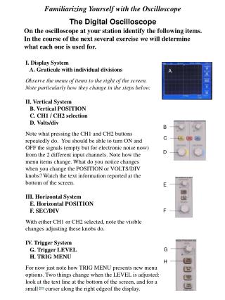
THE OSCILLOSCOPE shows graphically the behavior of an electrical signal qualitative measurement type rather than quantitative - low precision for both voltage and frequency. WORKING PRINCIPLE OF OSCILLOSCOPE. WORKING PRINCIPLE OF OSCILLOSCOPE. - Y AXIS - Vertical = Voltage :

E N D
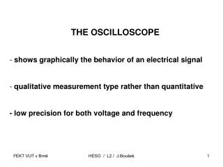
THE OSCILLOSCOPE • shows graphically the behavior of an electrical signal • qualitative measurement type rather than quantitative • - low precision for both voltage and frequency HESO / L2 / J.Boušek
WORKING PRINCIPLE OF OSCILLOSCOPE HESO / L2 / J.Boušek
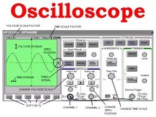
WORKING PRINCIPLE OF OSCILLOSCOPE - Y AXIS - Vertical = Voltage: V/Div; mV/Div - X AXIS - Horizontal =TIME BASE: s/Div; ms/Div; µs/Div; ns/Div - The vertical axis is driven by the input signal - The horizontal one by the internal time base HESO / L2 / J.Boušek
WORKING PRINCIPLE OF OSCILLOSCOPE • Example: 1V/Div (2V peak-to-peak); 10 µs/Div (25 kHz). • Without input signal : flat line.- Switching the the gain - change of divisions in Y axis. • Switching the time base - change of frequency HESO / L2 / J.Boušek
OSCILLOSCOPE - TRIGGER !! every scan draws a new trace !! result on the screen HESO / L2 / J.Boušek
OSCILLOSCOPE - TRIGGER Trigger event: - input signal crosses the trigger level - detection by voltage comparator - rising (positive) OR falling (negative) edge - trigger starts new scan For constantly repeated waves: 1) Identical trigger event restarts a new scan 2) New picture retrace exactly the previous shape Result : stable waveform on the grid (Signal is : triggered ; locked ; coupled ; hooked up) HESO / L2 / J.Boušek
OSCILLOSCOPE - TRIGGER • Trigger-setting • Select the edge - positive or negative. • 2) Set the trigger voltage level. HESO / L2 / J.Boušek
OSCILLOSCOPE - TRIGGER SINGLE - one shot mode - the scan starts only once at first trigger event - for next scan new start needed (manually) NORMAL - scan restarts only on trigger event - at the end waiting for next event - with no trigger events - not any trace AUTO - scan restarts automatically at each end of scan - trace is always shown without input signal - small signal does generate “trigger”- sliding waveforms HESO / L2 / J.Boušek
DIGITAL OSCILLOSCOPE HESO / L2 / J.Boušek
DIGITAL OSCILLOSCOPETektronix HESO / L2 / J.Boušek
OSCILLOSCOPE: Mind the ground connection !!!! HESO / L2 / J.Boušek
DIGITAL MULTIMETER METEX HESO / L2 / J.Boušek
DIGITAL MULTIMETER METEX HESO / L2 / J.Boušek
POWER SUPPLY: MIND THE TERMINALS !! HESO / L2 / J.Boušek
EXPERIMENTAL BOARD HESO / L2 / J.Boušek
EXPERIMENTAL BOARD: DIODE RECTIFIER HESO / L2 / J.Boušek