Download
1 / 20
200 likes | 347 Views
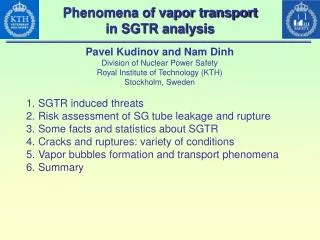
Phenomena of vapor transport in SGTR analysis. Pavel Kudinov and Nam Dinh Division of Nuclear Power Safety Royal Institute of Technology (KTH) Stockholm, Sweden. SGTR induced threats Risk assessment of SG tube leakage and rupture Some facts and statistics about SGTR

E N D
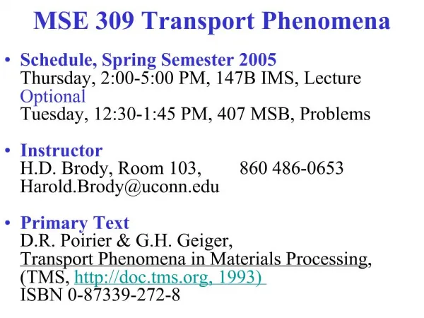
Phenomena of vapor transport in SGTR analysis Pavel Kudinov and Nam Dinh Division of Nuclear Power Safety Royal Institute of Technology (KTH) Stockholm, Sweden • SGTR induced threats • Risk assessment of SG tube leakage and rupture • Some facts and statistics about SGTR • Cracks and ruptures: variety of conditions • Vapor bubbles formation and transport phenomena • Summary
15..25 MPa, 330..500 oC SGTR 0.3 MPa, 400..500 oC LFR EFIT
SGTR-Induced Threats • Dynamic Loadings and Impact on Reactor Equipment Causing Secondary Failures • Transport of Steam to the Core and Core Voiding Reactivity Insertion with Potential for Power Excursion • Rupture-induced pressure shock wave • Steam Generation-Induced Sloshing • Steam Explosion • Steam Transport to the Reactor Core
Risk = Probability*Consequence 10-2 Not Acceptable Probability 1/year 10-3 10-4 10-5 End of Spectrum 10-6 Acceptable Consequences SG tube Leak and Rupture Risk Assessment SG tube Leak and Rupture are need to be evaluated against their Probability and Consequences SGTR in PWR SGTR in LFR, EFIT?
US NRC about tube degradation Tube Degradation During the early-to-mid 1970s, when all plants, except one, had mill annealed Alloy 600 steam generator tubes, thinning of the mill annealed Alloy 600 steam generator tube walls due to the chemistry of the water flowing around them was the dominant cause of tube degradation. However, all plants have changed their water chemistry control programs since then, virtually eliminating the problem with tube thinning. After tube thinning, tube denting became a primary concern in the mid to late-1970s. Denting results from the corrosion of the carbon steel support plates and the buildup of corrosion product in the crevices between tubes and the tube support plates. Measures have been taken to control denting, including changes in the chemistry of the secondary (i.e., non-radioactive) side of the plant. But other phenomena continue to cause tube cracking in plants with mill annealed Alloy 600 tubes. The extensive tube degradation at pressurized-water reactors (PWRs) with mill annealed Alloy 600 steam generator tubes has resulted in tube leaks, tube ruptures, and midcycle steam generator tube inspections. This degradation also led to the replacement of mill annealed Alloy 600 steam generators at a number of plants and contributed to the permanent shutdown of other plants. As mill annealed Alloy 600 steam generator tubes began exhibiting degradation in the early 1970s, the industry pursued improvements in the design of future steam generators to reduce the likelihood of corrosion. In the late 1970s, Alloy 600 tubes were subjected to a high temperature thermal treatment to improve the tubes’ resistance to corrosion. This thermal treatment process was first used on tubes installed in replacement steam generators put into service in the early 1980s. Thermally treated Alloy 600 is presently used in the steam generators at 17 plants. Although no significant degradation problems have been observed in plants with thermally treated Alloy 600 steam generator tubes, plants which replaced their steam generators since 1989 have primarily used tubes fabricated from thermally treated Alloy 690, which is believed to be even more corrosion resistant than thermally treated Alloy 600. Thermally treated Alloy 690 is presently used in the steam generators at 27 plants. Most of the newer steam generators, including all of the replacement steam generators, have features which make the tubes less susceptible to corrosion-related damage. These include using stainless steel tube support plates to minimize the likelihood of denting and new fabrication techniques to minimize mechanical stress on tubes.
Steam generator tube leakage USA NRC statistics 1990-2000
Known Steam Generator Tube Rupture Accidents in the World 1975-2002 Single SGTR is a rare event Multiple SGTR (MSGTR) has never occurred The reasons for reduction of SGTR frequency during past years are: • enhancement of SG production technology • chemistry control during operation • regular inspections and better regulation
Steam generator tube leakage Crack Morphology and Leak Rate First leak at 17.2MPa Maximum leak rate 4.28 l/min at 34.5MPa First leak at 25MPa Maximum leak rate 0.25 l/min at 31.7MPa Seong Sik Hwang, Hong Pyo Kim, Joung Soo Kim, Kenneth E. Kasza, Jangyul Park and William J. Shack ”Leak behavior of SCC degraded steam generator tubings of nuclear power plant” Nuclear Engineering and Design, Volume 235, Issue 23, December 2005, Pages 2477-2484
Wear degradation of steam generator tubs Seong Sik Hwang, Chan Namgung, Man Kyo Jung, Hong Pyo Kim and Joung Soo Kim ”Rupture pressure of wear degraded alloy 600 steam generator tubings” Journal of Nuclear Materials, In Press, Corrected Proof, Available online 16 May 2007
Burst characteristics for axial notches Seong Sik Hwang, Hong Pyo Kim and Joung Soo Kim “Evaluation of the burst characteristics for axial notches on SG tubings” Nuclear Engineering and Design, Volume 232, Issue 2, August 2004, P.139-143
Cracks and Ruptures: Variety of Initial Conditions • Flow rate depends on type, area and geometry of the opening • Sizes and Geometry of opening depends on initial degradation type and sizes • “Leakage before rupture” concept: based on fact that small leakage was often detected before (~several hours) the rupture had occurred. Although sudden ruptures also took place in the past • How to detect small leakage in lead cooled systems? • Leakage can produce small bubbles transportable to the core • …
Vapor bubbles formation and transport phenomena Shape and size of the bubbles: Wecrit ~ 10 => dmax~10 mm Eo(dmax)~10 => oblate ellipsoid
Steam Bubble Size Distribution Water: 22-24 MPa, 150-250 oC Beznosov et al, 2005 14x2 mm tube 10 mm discharge 2000 mm depth 52 mm Short wavelength due to high-pressure discharge. Measured average velocity of a bubble ~0.3 m/s
Vapor bubbles formation and transport phenomena Terminal speed of rising bubbles with dmax~10mm is ~0.2 - 0.3 m/s Effective density of vapor bubble (with water droplet inside) dose not affect terminal velocity Importance of resolution of 3D structure of the coolant flow for reliable prediction of void flux into the core Mendelson: Lehrer:
Size distributions of water droplets Beznosov et al, 2005
Life time of small droplet on a hot surface Time scale is ~10s of seconds for droplets ~1mm in diameter Guido Bleiker and Eckehard Specht Film evaporation of drops of different shape above a horizontal plate International Journal of Thermal Sciences, Volume 46, Issue 9, September 2007, Pages 835-841
Vapor bubbles formation and transport phenomena Evaporation of water droplet in a bubble will lead to growth of bubble diameter. Due to evaporation initial volume of void will increase ~2 times during ~10 seconds. Unfortunately, big (fast rising) bubbles most likely will not be stable due to high We number and high turbulence level. As a result we will have larger number of middle size bubbles up to 10 mm in diameter.
Summary • High uncertainty still remains in SGTR • Probability • Conditions • Consequences • With no operating experience SGTR may become bottleneck for licensing • More efforts needed in design for • Prevention of SGTR occurrence and • Mitigation of its consequences