Download
1 / 14
140 likes | 263 Views
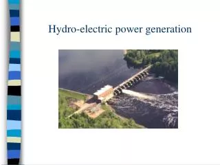
10.4 Electric Power Generation. http://www.power-technology.com/projects/laverton/images/FIGURE-2.jpg.

E N D
10.4 Electric Power Generation http://www.power-technology.com/projects/laverton/images/FIGURE-2.jpg
The basic principle of electric power generation is the same, whether the result is alternating or direct current: relative motion between a coil and a magnetic field induces an EMF, and hence a current, in the coil. In some generators, a coil is rotated in a magnetic field, but in large power stations, and in car alternators, the coils are stationary and an electromagnet rotates inside them. http://www.koehler.me.uk/animation/e_and_m_ac_gen_1.htm
(a) The field B and the plane of the area A of the loop are perpendicular and the amount of flux through the loop is maximum ΦB = BA. (b) After the loop has turned through a quarter of a revolution the plane of the loop is parallel to the field and the flux through the loop is zero. (c) The flux then increases but in the opposite sense relative to the loop; ΦB = –BA. It then decreases to zero again (d). This is followed by another maximum (e) and the cycle repeats. The green arrow indicates the normal to the plane of the area. The angle θ is between the field and the normal to the plane.
(a) The flux ΦB through the loop as a function of the angle θ between the field and the normal to the loop. (b) The rate of change of flux ΔΦB/Δt through the loop (and hence the EMF) as a function of the angle θ between the field and the normal to the loop. The loop is rotating at a steady speed.
The EMF is given by the rate of change of flux through the loop. The rate of change is the derivative. Hence, Note: θ = ωt, where ω is given by the angular velocity of the coil
(a) An AC generator uses simple slip rings to take the current from the coil. (b) A DC generator has a commutator to reverse the direction of the alternating current every half cycle and so produce a DC output. (c) Two (or more) coils may be used to smooth the DC output.
Power generated in large power stations is three-phase power. In designing a large generator, it would be inefficient use of space to simply have one pair of diametrically opposite coils around the rotating magnet. More particularly, it would result in uneven forces on the rotor as it turned through one cycle. For these reasons three pairs of coils at 120° to each other are used. It is these three phases that are carried by the three conductors in the high-voltage power lines we see coming from the power stations and terminal stations.