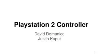
Playstation 2 Controller
Playstation 2 Controller. Kyle Yan Akshay Moorthy Yiping Kang. Outline. PS2 Controller Components Hardware Interface Bytes and Packets Transfer Mechanism Packet Structure Frequently Used Commands Example.

Playstation 2 Controller
E N D
Presentation Transcript
Playstation 2 Controller Kyle Yan AkshayMoorthy Yiping Kang
Outline • PS2 Controller Components • Hardware Interface • Bytes and Packets Transfer Mechanism • Packet Structure • Frequently Used Commands • Example http://www.walmart.com/ip/Sony-DualShock-2-PS2-Controller-Black-PlayStation-2/907869
Controller Components • 2x Analog Sticks • 16x Digital Buttons • Two Vibration Motors http://game-tips-etc.blogspot.com/2010/06/humble-ps2-controller.html
Buttons, Joysticks and Vibration • Buttons • A tiny curved conduction strip attached to the bottom • More pressure -> More conductivity • Joysticks • Two potentiometers below each joystick • Different angle -> Different resistance • Vibration • Two spinning motors (one big, one small) • Controlled separately • http://www.dansdata.com/tmsticks.htm
Wiring • Brown - Data: MISO • Orange - Command: MOSI • Grey - Vibration motor power: 6-9 V • Red - Power: 5 V. PS1 would work at 3.3V • Yellow - Attention: Must be pulled low before each group of bytes is sent/received and set high afterwards • Blue - Clock: Ranges from 100kHz to 500kHz, normally 500. • Green - Ack: Normally high and drops low for 12 us after each byte for half a clock cycle. Open collector output.
Brown: data Master-in-slave-out 2008 CuriousInverter.com
Orange: command Master-out-slave-in 2008 CuriousInverter.com
Grey - Vibration motor power 2008 CuriousInverter.com
Red - Power: 5 V. • PS1 would work at 3.3V 2008 CuriousInverter.com
Yellow - Attention: • Must be pulled low before each group of bytes is sent/received and set high afterwards 2008 CuriousInverter.com
Blue - Clock: • Ranges from 100kHz to 500kHz, normally 500. 2008 CuriousInverter.com
Green - Acknowledge • Normally high and drops low for 12 us after each byte for half a clock cycle. Open collector output. acknowledge 2008 CuriousInverter.com
How Bytes and Packets Are Transferred • Playstation sends command at the same time it receives one data through serial communication • Clock is held high until a byte is about to be send. Then it drops low to start a 8 cycles where command and data is simultaneously send and received. • Reads occurs on rising edge of the clock. • LSB is transferred first.
Sample Transaction 2008 CuriousInverter.com
Sample Transaction with Ack 2008 CuriousInverter.com
Sample Transaction with Attention 2008 CuriousInverter.com
Packet Structure • Header is always first 3 bytes • Most Common Commands • 0x42 - Polling buttons • 0x43 – Enter/Exit Config Mode • Device Modes • 0x4X – Digital Mode • 0x7X – Analog Mode • 0xFX – Config Mode
Main Polling Command (0x42) • Get digital responses from buttons, • also control the vibration motors. Motors Control & Button Digital Output 2008 CuriousInverter.com
Button Mapping • Byte 4 and 5 – Command/Mode dependent data • Buttons are mapped to bytes 4 and 5 (active low) 2008 CuriousInverter.com
Main Polling Command (0x42) • Get analog response from the joysticks and buttons Analog Joystick Output (optional) Button Analog Output (optional) 2008 CuriousInverter.com
Enter/Exit Config Command (0x43) • Config mode allows you to change multiple settings • Command.4 • 0x01 Enter Config • 0x00 Exit Config 2008 CuriousInverter.com
Switching Between Modes (0x44) • Command = 0x44 • Command.4 determines mode • 0x00 – Analog Mode • 0x01 – Digital Mode 2008 CuriousInverter.com
Other Config Commands • Adding/Removing responses • Vibration control • Get more status info
Walkthrough Example Enter config mode Map motors to byte 4 and 5 Config the controller to return all values Exit config mode Main polling !
Walkthrough Example Enter config mode Map motors to byte 4 and 5 Config the controller to return all values Exit config mode Main polling ! 0x00 – small motor 0x01 – big motor Map byte 4 to big motor byte 5 to small motor
Walkthrough Example Enter config mode Map motors to byte 4 and 5 Config the controller to return all values Exit config mode Main polling ! • Byte 4 , byte 5 and the two LSB of byte 6 = 18 bits • Corresponding to 18 bytes in data under main polling command • ‘1’ indicates the response to be present in the data
Walkthrough Example Enter config mode Map motors to byte 4 and 5 Config the controller to return all values Exit config mode Main polling !
Walkthrough Example Motor Control Enter config mode Map motors to byte 4 and 5 Config the controller to return all values Exit config mode Main polling ! Button Pressure (Right fully pressed here) Analog Stick Digital
Reference • Spinning Motor http://www.dansdata.com/tmsticks.htm • Interfacing with a PS2 controller http://store.curiousinventor.com/guides/PS2/ http://www.lynxmotion.com/images/files/ps2cmd01.txt How buttons and joystick works http://www.howstuffworks.com/ps23.htm