Media Access Protocols
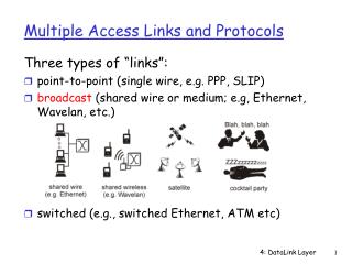
Media Access Protocols. …. Multiple Access Media. Multiple senders on some media ALL nodes will receive a copy of the transmitted signal Topologies Bus (Ethernet) Radio, Satellite Token Ring Need methods to mediate access Fair arbitration Good performance. Multiple Access Media.

Media Access Protocols
E N D
Presentation Transcript
… Multiple Access Media • Multiple senders on some media • ALL nodes will receive a copy of the transmitted signal • Topologies • Bus (Ethernet) • Radio, Satellite • Token Ring • Need methods to mediate access • Fair arbitration • Good performance
Multiple Access Media • Typical assumptions • Communication needs vary • Over time • Between hosts • Network is not fully utilized • Recall methods for multiplexing • Frequency-division multiplexing (FDM) • Fixed – one frequency assigned to each host • Dynamic – frequencies assigned on demand (hard to do) • Time-division multiplexing (TDM) • Fixed – one timeslot (within a round of timeslots) assigned per host • Dynamic – timeslots assigned to hosts on demand (e.g. FCFS) • AKA Statistical time-division multiplexing (STDM) • STDM most appropriate with stated assumptions
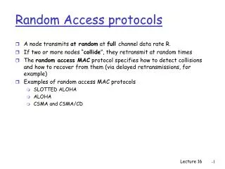
Multiple Access Media • Problem: demands can conflict, e.g., two hosts send simultaneously • STDM does not address problem • Solution is a medium access control (MAC) algorithm • Two solutions (of many) • Carrier sense multiple access with collision detection (CSMA/CD) • Send only if medium is idle • Stop sending immediately if collision detected • Try again later • Token ring pass a token around a ring; only token holder can send
Bus Topology: Shared Ethernet, Token Bus Ring Topology: Multihop FDDI, IEEE 802.5 Wireless: Shared IEEE 802.11 Types of Shared Link Networks
Ethernet • History • Developed by Xerox PARC, mid 70s • Roots in Aloha packet radio network • Standardized by Xerox, DEC and Intel in 1978 • Bandwidth • 10 Mbps – 1000 Mbps • Problem • Distributed algorithm that provides fair efficient access to a share medium
Ethernet - CSMA/CD • CS – Carrier Sense • Nodes can distinguish between an idle and a busy link • MA - Multiple Access • A set of nodes send and receive frames over a shared link • CD – Collision Detection • Nodes listen during transmission to determine if there has been interference • Stop if interference occurred, and try later.
T ransceiver Ethernet cable Adaptor Host Original Ethernet Hardware • Coaxial Cable (known as 10Base5 or thicknet) • 10 Mb/sec (hence 10) • Up to 500m (hence 5) • Baseband system (hence base) • Taps • > 2.5m apart • Transceiver • Idle detection • Sends/Receives signal • Adaptor • Implements all the logic
Repeaters • A repeater amplifies digital signals • Up to four repeaters allowed between two nodes • I.e., max of 2500 meters. • Maximum of 1024 nodes per Ethernet … … … … Repeater Host
10Base2 • Known as thinnet, a thinner coax cable • Up to 200 m • 10 Mb/sec • Cannot tap into it (too thin) • Use a T-joint to daisy-chain machines together. T-joint Ethernet cable Transceiver Adaptor Host
10BaseT • T stands for “twisted pair” (two thin cables braided together) • Limited to 100 m in length • Can run from 10 up to 1000 Mb/sec • Connected via hubs, a hub is a multi-way repeater. Hub Hub
Gigabit Ethernet • I don’t know much about it • However, you cannot use hubs, i.e., must be point-to-point. • You can use 10BaseT cable.
10Mb Ethernet Specifications (Xerox, 1980’s) • Broadcast (every signal sent is heard by all nodes) • Encoding • Manchester • 10 Mbps -> Transmission at 20Mhz • Framing • Sentinel byte marks end of frame • Bit oriented (similar to HDLC????) • Data-dependent length???? • Error Detection • 32-bit CRC
10Mb Ethernet Frame Format 7 1 6 6 2 46-1500 4 1 End of Frame Source Address CRC Destination Address Body + Padding Start of Frame Type Preamble
Ethernet Frame Components • Preamble + Start of Frame • 7 bytes of 10101010, 1 byte of 10101011, why this pattern? • Encoded as 10Mhz square wave • Synchronize receiver’s clock • Source and Destination Address • Unique unicast Ethernet addresses • 20 bit manufacturer prefix + 28 bit ID • Broadcast address: FF:FF:FF:FF:FF:FF • Multicast address: MSB set (80:00:…)
Ethernet Frame Components • Type • 2 – bytes • Used to demultiplex higher layers • Body + Padding • Minimum data size = 46 (minimum frame size = 64) • Data padded to minimum value • Maximum data size = 1500
Ethernet Frame Components • CRC • 4 byte • End of frame marker (no length field) • 1 byte (01111110 flag??? or coding violations?) • Xerox vs. IEEE 802.3 • 802.3 replaces type with length • 802.3 no EOF • Just stop transmitting at the end • No coding violations • No bit insertion • How to determine type? First 2 bytes in “data” is type.
Cookie Jar Assume there is a cookie jar We all try to get a cookie Only one hand at a time fits in the cookie jar We are blindfolded and have earplugs What do we do so we all get a cookie?
Types of CSMA • 1-persistent CSMA: (Ethernet is 1 persistent) • if the channel is idle, transmit a frame with probability 1 (do it). • if the channel is busy, continue sensing until it becomes free, then xmit • if a collision occurs, wait for a random length of time and try again. • p-persistent CSMA: • if the channel is idle, transmit with a probability p, and defer transmission to the next slot (a timeslot is a round-trip delay) with a probability q = (1 - p). • if the channel is busy, continue sensing until it is idle then try again. • if a collision occurs, wait for a random length of time to try again. • non-persistent CSMA: • if the channel is idle, transmit the frame. • if the channel is busy, wait for a random length of time and try again. • if a collision occurs, wait for a random length of time and try again.
Collisions in 1-persistent CSMA 2 • C is ready to transmit, but must wait since channel is busy • A is ready to transmit, but must wait since channel is busyWhat would happen if we use p-persistent (p < 1)? A Collision B C 1 time
Ethernet MAC Algorithm • Sender/Transmitter • If line is idle (carrier sensed) • Send immediately • Send maximum of 1500B data (1527B total) • Wait 9.6 s before sending again • If line is busy (no carrier sense) • Wait until line becomes idle • Send immediately (1-persistent) • If collision detected • Stop sending data and send a jamming signal • Try again later
Collision Detection • In Ethernet, you can almost immediately detect that a collision occurs. This is done by listening to the channel while you transmit. • If a collision occurs, abort (don’t wait until you transmit the whole frame, thus you save time). • How long is it before you detect a collision? 2T A A detects the collision here B C detects the collision here C T = end-to-end propagation delay
Collision Detection (continued) • A transmits for at least 2T seconds before learning a collision occurred. • Thus, the minimumpacket size a station can transmit is 2T(channel bandwidth) • 802.3 • 2T is bounded to 51.2s • At 10Mbps 51.2s = 512b or 64B • Packet length 64B • Jam after collision • Ensures that all hosts notice the collision
A B C Jam time Jamming • If a collision occurs, the sender aborts transmission and sends 4 bytes of random signals (a jamming signal). This ensures all nodes do not accept the message. • Any packet received with less than 64 bytes is assumed to be from a collision.
Retransmission • How long should a host wait to retry after a collision? (rexmit the SAME packet, you don’t start a new packet until the previous one is transmitted). • Binary exponential backoff • Maximum backoff doubles with each consecutive failure (for the same packet) • After N consecutive failures, pick an N-bit number • 2N discrete possibilities from 0 to maximum
Binary Exponential Backoffhow long to wait after collision Choices after 2 collisions Choices after 1 collision 0 1(2T) 2(2T) 3(2T) Why slots of size 2T?
Truncated Binary Exponential Backoff (TBEB) • Goal: to quickly resolve contention among 1024 stations • Let i = # of retransmission attempts for the same packet (after 1st collision, i = 1) • n = min (i, 10) {hence, "truncated"} • Pick a uniformly distributed random number from 0 up to 2n -1 • y := rand(0, 2n -1) • Wait for y time-slots (51.2 sec per timeslot = 2T) • When channel goes idle again, retransmit. If collision go to 1 • If i = 16, abort and declare failure (throw message away) • Why change the interval of the random number? • If y := rand(0,1) always, and we have 1000 stations, 999 would have to pick 1 and one pick 0 to avoid a collision (which is unlikely) • If y := rand(0, 1023) and have only two stations, the delay is too large
Frame Reception • Sender handles all access control • Receiver simply pulls the frame from the network • Ethernet controller/card • Sees all frames • Selectively passes frames to host processor • Acceptable frames • Addressed to host • Addressed to broadcast • Addressed to multicast address to which host belongs • Anything (if in promiscuous mode) • Need this for packet sniffers/TCPDump
Ethernet in Practice • Number of hosts • Limited to 200 in practice, standard allows 1024 • Range • Typically much shorter than 2.5km limit in standard • Round Trip Time • Typically 5 or 10 s, not 50 • Flow Control • Higher level flow control limits load (e.g. TCP) • Topology • Star (hubs, and bridges/switches – discussed later) is easier to administer than bus
Performance • Channel efficiency: 1/(1 + 2BLe/cF), where • B = bandwidth of the channel (inverse to B, if F fixed then successful packets hold the channel for a smaller time, after xmission the opportunity for contention occurs again) • L = length of the cable (inverse to L, greater chance of collision) • e = usual, 2.718 ... (constant) • F = frame length (proportional to F, longer F means more time without collision) • c = propagation speed (constant, usually 2/3 speed of light) • Under the best assumptions, each frame on average is transmitted e times. • Note B increases with technology. To maintain efficiency, F must increase or L decrease.
WE WILL SKIP TOKENG RING …. GO TO WIRELESS
Token Ring Overview • Examples • 16Mbps IEEE 802.5 (based on earlier IBM ring) • 100Mbps Fiber Distributed Data Interface (FDDI) • Frames flow in one direction: upstream to downstream • Each station “buffers” a couple of bits of each frame before forwarding them to the next station • Special bit pattern (token) rotates around ring • Before transmitting, station most seize (remove) the token • After transmitting, the station reinserts the token. token
Example of Operation • Token rotates around the ring • The token should “fit” in the ring (I should not receive the token while I transmit it!) • Otherwise, the “monitor” station adds additional buffering. • Station wishing to transmit seizes the token token token
Example of Operation • Station begins to transmit its data frame. • The difference between the data frame and the token is just one bit in the header. • Thus, station can quickly convert a token to a data frame • The data frame MAY wrap around the entire ring • Destination makes a COPY of data frame, but allows it to go through • Sending station removes the bits as they come in. data data
Example of Operation • Station sends the token immediately after transmitting its data (early release) • Alternatively, send the token after the entire data has been removed (delayed release) • Early release gives better throughput, why? • Most systems are early release data token • Multicast and broadcast addresses are supported.
Fairness • Token release by the sender gives you round-robin service (fair) • What if token is released by the destination? • A sends data to B • B receives data, sends token to A • X does not wish to send, forwards token to A • A sends again to B • Y is starved! X B A Y
Physical Fault Tolerance • What if a station fails? • Stations are connected to the ring using electronic relays • The relay is open as long as the station has power (is healthy) • If no power from station, the relay closes. Host Host From previous T o next From previous T o next host host host host Relay Relay
Host MSAU Host Host From previous MSAU Host T o next MSAU Multistation Access Units • Several relays are packed into a single box • Gives a common “meeting point” for stations • Creates more like a “star” configuration
Token Holding Time and Rotation Time(IBM Token Ring) • Token Holding Time (THT) is a constant • It is an upper bound on how long to hold the token • If infinity, it can starve other stations. • If too small, inefficient • E.g., if only for one packet, is wasteful if only one station transmits • Wait for token to go around before transmitting again. • It is set to 10 milliseconds. • Token Rotation Time (TRT) • Measurement done at each node. • It is how long it takes the token to traverse the ring. • TRT≤ ActiveNodes x THT + RingLatency
Frame Format 8 8 8 48 48 Variable 32 8 8 Start Access Upper Dest Src End Frame • Uses differential manchester encoding • Coding violations are used at the delimiters to mark the start/end of frame • Reliable delivery (sort of) • Two bits, A and C, in the trailer • If the destination sees the frame, it sets the A bit (acknowledgment) • If the destination copies the frame, it sets the C bit (copy) • If A is set but C is not the station may not have copied the frame due to perhaps lack of buffer space. • There is a strict priority scheme (access control byte) • This is needed if the THT is large and a small high priority message can’t wait (see next slide) Body Checksum delimiter control Protocol addr addr delimiter status
Priority Scheme • Every packet is assigned a priority between 0 (lowest) and 7 (highest) with three priority bits in its header. • When a station receives the token, the station transmits any queued packets that are at or above the priority of the token, higher priority packets first. • queued packets that have a priority less than that of the token must wait until a lower priority token is received by the station. • As packets (data or token) are repeated by non-transmitting stations, these stations may reserve the priority of the token by setting the reservation bits in the packet header (3 bits) to the highest priority packet that they have waiting • You can’t lower the existing reservation bits though.
Priority Scheme (continued) • When a station has completed its transmission, it retransmits the token at the greater of the value of • the current token priority and • the current reservation field. • If a station raises the token’s priority from X to Y, it is responsible for lowering the token’s priority from Y to X if it later receives a priority Y token with no reservations higher than X.
802.5 Monitor • Responsible for • Inserting delay (ensure the token fits in the ring) • Detect Token presence • Should see a token at least once per max TRT, if not insert one • Check for corrupted frames • Must be drained off the ring, the source id may be corrupted, so the source will not remove it. • Check for orphaned frames (source died, won’t drain frame) • There is a “monitor bit” in the header • Monitor station sets bit first time it sees the packet • If monitor sees packet again, it discards packet
Electing A Monitor • Periodically, the monitor transmits a “monitor present” frame • If none is received for some time, a new monitor must be elected. • Each station detecting no monitor transmits a "claim token" frame with its address. • If this frame circulates back to the sender with the same address, it becomes the monitor. • If some other station is also trying to become the monitor, • if the address of the sender is higher than its own, the first station will circulate the other "claim token" frame • else it removes the claim from the ring. • Only the contending frame with the highest address will circulate all the way around the ring.
8 8 48 48 8 32 24 Start of Dest Src End of Control Body CRC Status frame addr addr frame FDDI • Fiber Distributed Data Interface • Started using optical (hence fiber) • Standard expanded to lots of other media • NRZI with 4B/5B encoding • Each station imposes a delay (from 9 to 80 bits) • 5 bit delay is 50 ns • Maximum of 500 Stations • No more than 2 km between hosts • Upper limit of 100km • Need 200km of fiber for dual ring
It is a self-healing dual ring (counter-rotating) • Outer ring used in normal traffic • Inner ring only used in case of failure
Concentrator • Too expensive sometimes for all stations to have hardware for two rings. • Concentrator connects multiple Single Attachment Stations (SAS) • If any station fails, an optical relay bypasses station • Similar to MSAU’s in 802.5 Concentrator SAS SAS SAS
Timed Token Algorithm (FDDI) • Target Token Rotation Time (TTRT) • agreed-upon “upper bound” on TRT • TRT – measures the time between consecutive arrivals of the token • If TRT < TTRT • The token is “early” • Station can transmit up to THT = TTRT – TRT seconds of data • THT is not a constant anymore. • If TRT ≥ TTRT • The token is “late” • Cannot transmit, just forward token • Is this fair?
Asynchronous and Synchronous Traffic • Synchronous traffic – delay sensitive • You can always transmit synchronous packets when you receive the token • Each station i has an upper bound Hi on the amount of synchronous traffic that it can send per token • Asynchronous traffic – not delay sensitive • Can only send asynchronous traffic if the token is early • Note • Ring-Latency + (Sum, over all i, Hi) ≤ TTRT
How late? • Token rotates freely around the ring • Then, a station receives the token, TRT = 0, thus transmits asynch traffic for TTRT seconds • Then, all other stations can transmit their synchronous traffic • Note that this can add up to TTRT • No asynch traffic is xmitted (token is late) • Thus, TRT at the next round could be 2*TTRT! • Back-to-back 2*TTRT rotation times are not possible.