Download
1 / 8
90 likes | 215 Views
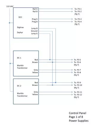
110 VAC. Rail A Rail B Prog A Prog B Jump B Ground Jump A. To: P3-1 To: P3-2 ( Pg 7). DCC Digitrax Zephyr. To: P3-3 To: P3-4 ( Pg 7). DC-1 Marklin Transformer. Red Brown Grey Yellow. To: P3-5 To: P3-6 ( Pg 7). To: P3-7 To: P3-8 ( Pg 7). Red Brown Grey Yellow.

E N D
110 VAC Rail A Rail B Prog A Prog B Jump B Ground Jump A To: P3-1 To: P3-2 (Pg 7) DCC Digitrax Zephyr To: P3-3 To: P3-4 (Pg 7) DC-1 Marklin Transformer Red Brown Grey Yellow To: P3-5 To: P3-6 (Pg 7) To: P3-7 To: P3-8 (Pg 7) Red Brown Grey Yellow To: P3-9 To: P3-10 (Pg 7) DC-2 Marklin Transformer To: P3-11 To: P3-12 (Pg 7) Control Panel Page 1 of 8 Power Supplies
ACC-1A ACC-1B (Pg 7) ACC-2A ACC-2B (Pg 7) To: P1-22 To: P1-23 SW1 To: P1-1 SW7 To: P1-13 To: P1-2 To: P1-14 SW2 To: P1-3 SW8 To: P1-15 To: P1-4 To: P1-16 SW3 To: P1-5 SW9 To: P1-17 To: P1-6 To: P1-18 SW10 SW4 To: P1-7 To: P1-8 To: P1-19 SW11 SW5 To: P1-9 To: P1-10 To: P1-20 SW12 SW6 To: P1-11 To: P1-21 To: P1-12 Control Panel Page 2 of 8 Turnout Control
DC-1A DC-1B (Pg-7) SW13 P1 To: Sw24 P1-A P2 To: Sw24 P2-A SW14 P1 To: Sw24 P3-A P2 To: Sw24 P4-A SW15 P1 To: Sw24 P5-A P2 To: Sw24 P6-A P1 To: Sw24 P7-A P2 To: Sw24 P8-A SW16 P1 To: Sw24 P9-A P2 To: Sw24 P10-A SW17 P1 To: Sw24 P11-A P2 To: Sw24 P12-A Control Panel Page 3 of 8 Track Control SW18 DC-2A DC-2B (Pg-7)
AR-1A AR-1B DCC-A DCC-B (Pg 7) Sw13P1 (Pg 3) A To: J2-1 (Pg 6) B P1 Sw13P2 (Pg 3) A To: J2-2 (Pg6) B P2 A Sw14P1 (Pg 3) SW19 B To: J2-3 (Pg6) P3 Prog-A (Pg 7) Sw14P2(Pg 3) A To: J2-13 (Pg6) To: J2-4 (Pg6) B P4 To: J2-14 (Pg6) Sw15P1 (Pg 3) A Prog-B (Pg 7) To: J2-5 (Pg6) B P5 Sw15P2 (Pg 3) A To: J2-6 (Pg6) B P6 Sw16P1 (Pg 3) A To: J2-7 (Pg6) B P7 Sw16P2 (Pg 3) A To: J2-8 (Pg6) B P8 A Sw17P1 (Pg 3) To: J2-9 (Pg 6) B P9 Sw17P2 (Pg 3) A To: J2-10 (Pg 6) B P10 A Sw18P1 (Pg 3) B To: J2-11 (Pg 6) P11 Sw18P2 (Pg 3) A To: J2-12 (Pg 6) B P12 Control Panel Page 4 of 8 Track Power Switch SW24 (12P2T) AR-2A AR-2B (Pg 7)
Sw1-1 (Pg 2) Sw1-2 (Pg 2) Sw2-1 (Pg 2) Sw2-2 (Pg 2) Sw3-1 (Pg 2) Sw3-2 (Pg 2) Sw4-1 (Pg 2) Sw4-2 (Pg 2) Sw5-1 (Pg 2) Sw5-2 (Pg 2) Sw6-1 (Pg 2) Sw6-2 (Pg 2) Sw7-1 (Pg 2) Sw7-2 (Pg 2) Sw8-1 (Pg 2) Sw8-2 (Pg 2) Sw9-1 (Pg 2) Sw9-2 (Pg 2) Sw10 (Pg 2) Sw11 (Pg 2) Sw12 (Pg 2) ACC-1B ACC-2B 1 2 3 4 5 6 7 8 9 10 11 12 13 14 15 16 17 18 19 20 21 22 23 24 25 1 2 3 4 5 6 7 8 9 10 11 12 13 14 15 16 17 18 19 20 21 22 23 24 25 Lower Loop Left Turnout Close Lower Loop Left Turnout Throw Lower Loop Right Turnout Close Lower Loop Right Turnout Throw Upper Loop Left Turnout Close Upper Loop Left Turnout Throw Upper Loop Right Turnout Close Upper Loop Right Turnout Throw Yard Left Pair Turnouts Throw Yard Left Pair Turnouts Close Yard Right Pair Turnouts Throw Yard Right Pair Turnouts Close Spur 1 Turnout Throw Spur 1 Turnout Close Spur 2 Turnout Throw Spur 2 Turnout Close Programming Spur Turnout Throw Programming Spur Turnout Close Lower Loop Uncoupler Upper Loop Uncoupler Programming Spur Uncoupler Common for Pins 1-12 Common for Pins 13-21 Spare Spare P1 J1 Control Panel Railroad (Reference) Control Panel Page 5 of 8 Connector P1
Sw24-P1 (Pg 4) Sw24-P2 (Pg 4) Sw24-P3 (Pg 4) Sw24-P4 (Pg 4) Sw24-P5 (Pg 4) Sw24-P6 (Pg 4) Sw24-P7 (Pg 4) Sw24P-8 (Pg 4) Sw24P-9 (Pg4) Sw24-P10 (Pg4) Sw24-P11 (Pg4) Sw24-P12 (Pg4) Sw-19-A (Pg4) Sw-19-B (Pg4) 1 2 3 4 5 6 7 8 9 10 11 12 13 14 15 16 17 18 19 20 21 22 23 24 25 1 2 3 4 5 6 7 8 9 10 11 12 13 14 15 16 17 18 19 20 21 22 23 24 25 Upper Loop Block 1 Track Power A Upper Loop Block 1 Track Power B Upper Loop Block 2 Track Power A Upper Loop Block 2 Track Power B Upper Loop Block 3 Track Power A Upper Loop Block 3 Track Power B Lower Loop Block 1 Track Power A Lower Loop Block 1 Track Power B Lower Loop Block 2 Track Power A Lower Loop Block 2 Track Power B Lower Loop Block 3 Track Power A Lower Loop Block 3 Track Power B Programming Spur Track Power A Programming Spur Track Power B Spare Spare Spare Spare Spare Spare Spare Spare Spare Spare Spare J2 P2 Control Panel Railroad (Reference) Note: Track Power A (red) connects to the outside rail (or the nearest rail to you) in a circle and Track Power B (black) connects to the inside rail. This results in a forward direction which is defined as counter clockwise. Control Panel Page 6 of 8 Connector J2
Rail A (Pg 1) Rail B (Pg 1) Prog-A (Pg 1) Prog-B (Pg 1) DC-1A (Pg 1) DC-1B (Pg 1) ACC-1A(Pg 1) ACC-1B(Pg 1) DC-2A(Pg1) DC-2B(Pg1) ACC-2A(Pg1) ACC-2B(Pg1) 1 2 3 4 5 6 7 8 9 10 11 12 1 2 3 4 5 6 7 8 9 10 11 12 A in (Pg 7) B in (Pg 7) Prog-A (Pg 4) Prog-B (Pg 4) DC-1A (Pg 3) DC-1B (Pg 3) ACC-1A (Pg 2) ACC-1B (Pg 2) DC-2A (Pg 3) DC-2B (Pg 3) ACC-2A (Pg 2) ACC-2B (Pg 2) P3 J3 Control Panel Power Supply Sw21 Sw20 Note: SW20 through SW23 provide the capability to operate a DC loco with the DCC controller by allowing the operator to manually switch the otherwise automatic reversing loops. After entering the loop and stopping the loco, the operator depresses the pushbutton switch located near the exit turnout, reverses the throttle, then restarts the loco. UP6Z J3-1 J3-2 (Pg 7) A in B in 4V X A in B in Out A Out B To: AR-1A To: AR-1B (Pg 4) AR1-1 To: DCC-A To: DCC-B (Pg 4) Sw23 Sw22 A in B in Out A Out B To: AR-2A To: AR-2B (Pg 4) Control Panel Page 7 of 8 Connector P3, J3 AR1-2
Control Panel Page 8 of 8 Parts List