Download
1 / 79
800 likes | 862 Views
Explore cutting-edge mass spectrometry techniques including MALDI-TOF, FT-ICR, and ion mirrors. Learn about detectors with high efficiency and sensitivity, and understand the principles behind mass analyzer design. Discover how to optimize ion count for peak performance.

E N D
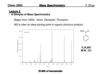
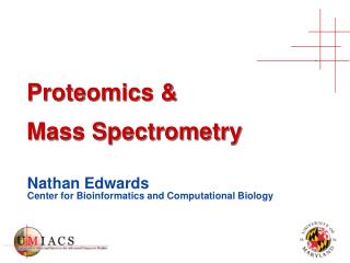
Biochem 523b: Advanced Physical Methods: Mass Spectrometry, X-ray Crystallography and NMR A. Mass Spectrometry Lecture 2 Mass analyzers Time of flight (MALDI-TOF), TOF-TOF Quadrupole Ion trap Linear ion trap Q-TOF FT ICR MS Orbitrap
Detectors for mass spectrometry Converts energy of incoming ions into a current signal that will be registered by the electronic devices and computer of the acquisition system. When the incoming ions hit the detector, the energy of that impact causes emission of secondary electrons or photons. The number of secondary Particles created by an impact depends on the energy and velocity of the incoming ion. If all the particles are accelerated to the same kinetic energy as in TOF Analyzer. The detection sensitivity is lower for high mass (slow) ions than for low mass (fast) Ions. To increase sensitivity Ions can be post-accelerated before striking the detector. Detector should have high efficiency for converting energy of incoming ion to electrons or photons, a liner response, low noise short recovery time (to avoid saturation) an minimal variation in transit time (narrow peak width)
Microchannel plates Parallel arrays of channel electron multiplier
Ions are counted. The ions counted are often reported in counts per • seconds (Cps). • To minimize statistical errors more ions should be measured by • using longer acquisition time • adding (averaging) many individual scans • have enough ions produced in the source (eg raise source • voltage or T) • d) and efficiently transported through the MS • Detectors can get saturated. • MCPs need periodical replacement
Matrix Assisted Laser Desorption/Ionization Sample is co-crystallized with matrix (solid) Formation of singly charged ions Koichi Tanaka, Nobel Prize 2002
Absorb UV light, crystallize easily, sublimate easily and transfer proton to analyte
MALDI-TOF… The energy (E) uptake by an ion of charge q and mass m is equal to an integer number z of electrons charges e, and thus q = ez E = qU = ez U = Ekin = ½ mv2 v = 2 ezU m Since we the velocity is related to the time, we can relate the mass to the time: t = d/v d d m t = t = z 2 ezU 2 eU m Time to drift is proportional to square root of m/z Smaller ions will arrive faster than heavier ions
MALDI Time-of-Flight (TOF) Heavier ions arrived later Source Drift region (d) d d m t = t = z 2 ezU 2 eU m
MALDI-Time-of-Flight Mass Spectrometer MALDI TOF (linear) Mass range = 800-200,000 Sensitivity and accuracy decrease rapidly with size !
MALDI with Reflectron Laser pulse Detector source Similar Ions may possess slightly different energies and arrive at different times = broad peaks ie poor resolution Ions with more kinetic energy will penetrate more deeply Laser pulse Refocussing Detector Ion Mirror (reflectron)
MALDI –Delayed Extraction Earlier instruments use continuous extraction of ions, ie accelerating voltage was applied during and after laser pulse. Ions are allowed to form in a field free environment. A few hundeds of nanoseconds later and after the laser pulse has terminated, a fast pulse extracting voltage is applied. Alternatively a two stage accelerating voltage can be applied which diminishes the energy spread. The resolving power is increased by a factor of 3-4 for linear MALDI and by a factor of 2-3 for MALDI with reflectron (MALDI-R) up to 10,000-20,000. This additional resolution is need for resolving more complex mixtures and provide sufficient mass accuracy. Use MCP detectors: velocity (mass) sensitive
Reflectron reduces the ion transmission ie lost in sensitivity. depending on the reflectron mass above a certain m/z are not observed. ~4,000 on Micromass ~10,000 on Bruker, ABI) Most MALDI TOF have two detectors one operating in one linear mode (for higher masses eg proteins) and one in reflectron mode for higher resolution and mass accuracy and eg tryptic peptides. One major disadvantage of MALDI TOF is that it cannot perform MS/MS of peptides other than in the postsource decay mode (PSD) which is gives generally poor coverage. Another configuration is the orthogonal TOF (o-TOF): Source is orthogonal to mass analyzer. Ions are pushed toward the detector by applying a voltage to the incoming ions. l TOF mass analyzer can be combined with other mass analyzers such as TOF-TOF and Q-TOF instruments
TOF-TOF MS for (MS/MS) Parent ion selection is done by ion gates deflecting the undesired ions from the collision cell. The fragment are re-accelerated towards the detector source. Katalin F. Medzihradszky, J. M. Campbell et al., Anal Chem 2000 72 pp 552 - 558
ABI/Sciex 4800 TOF/TOF (second generation) Collision cell Detector linear Detector of reflector Source 2 Ion mirror Timed ion selector Decelleration stack optics prior to collision cell enable the kinetic energy ot the precursor Ions entering the collision cell to be tuned for controlled fragmentation. camera laser
ABI 4700 ABI 4800
TOF/TOF Instruments are ideal for HTP peptide identification by MALDI Extremely fast MS and MS/MS (10/sec) with excellent sensitivity (low femtomole) and good mass accuracy (~15 ppm). Collision energy can be very high and varied. High collision energy allow for fragmentation of the side chains: TOF/TOF is the only MS/MS instrument capable of distinguishing Leu and Ile. Not cheap: ~700K!
Quadrupole mass analyzers Device that separates ions in a quadrupole electric field based on their m/z . The quadrupole electric field is created by a set of four parallel rods on which both a DC and alternating voltage (RF) are applied. By changing the applied field only some m/z will be transmitted from one end of the quadrupole rods to the detector. For a given set of voltage only a certain m/z range will be transmitted. To obtain the full mass spectrum, perform scan for all m/z in their individual stability region. Mass range: 10-4000 Da Resolution: Operated at unit mass resolution up to ~2,000 Da can be increased to ~4,000 Mass accuracy : ~0.1-0.2 Da Scan speed: 5000Da/per second
Ions are lost Mass filter; complete spectrum is obtained by scanning whole range Mass range 50- 4,000 Da
1. DC only: no masses are transmitted 2. RF ONLY: no separation, all ions are transmittted 3. DC + RF only ions with narrow mass range are transmitted 4. Movement in 3 directions
Quadrupole as Mass Filter: Ideally hyperbolic rods but are more difficult to produce so use cylindrical rods
Rod potential Fo: Fox = U – V cos wt Foy = - U + V cos wt U is the DC potential and V cos wt is the time dependent RF voltage in which V is the amplitude, f = w/2p the radiofrequency, and t, time. f is fixed at ~1MHz
Movement of ions is relatively complex; x,y,z directions The ions emerging form the source are accelerated in at the entrance of the quadrupole (z direction) over a potential of 5-20 v. (The resolution will be negatively affected by higher velocity). All ions will be affected by the force exerted by the fields in the x and y directions. Consider the x plane:. Fox = U – V cos wt. U is positive. Large positive ions are less responsive to RF voltage and will be repulsed towards the middle of the x plane. The low mass positive ions respond faster to the RF voltage (less mass inertia). Once every cycle the sum of the DC and RF voltage components will be negative for a short time and the passing ions will experience an attractive force. If the mass is low enough the ion will be accelerated toward one of the x electrode and hit before it becomes positive again (Lost!). This pair of rod act as high mass filter
Foy = - U + V cos wt In the y direction pair of electrode will act as a low mass filter. The DC potential U is negative and the high mass ions are more responsive to the DC component (the RF is high and the potentials tends to average out). The larger positive ions will be slowly dragged to the negatively charged electrode. The low mass will also experience an attractive force but will respond more to positive RF potential forcing them more in the middle between the y electrodes. Analogy with ball on top of a curve surface. It is unstable but by wiggling the cylinder back in forth, the ball will not fall.
Ion Motion and Stability Diagram The Motion of an ion traveling in a quadrupole field is described by the Mathieu equation: d2u + (au- 2qucos2x) u = 0 dx2 Where x = wt /2, and u represents x or y. The Mathieu parameters au and qu are defined as au = 8qchU w2r02m qu = 4qchV w2r02m (RF) and (DC) Where r0 is half the distance between opposite rods, qch is the charge and m the mass. Substituting for u for x and y gives au = ax = - ay and qu = qx = - qy Only certain combinations of a and qgives stable solutions to the Mathieu eqn that is, ions passing through the quadrupole. Moreover only the a/q combinations that gives stable solutions for both the x and y directions will be useful.
Select for only one m/z. Higher resolution but loose sensitivity Larger m/z range Less resolution Stability region I expanded Common to both x and y Change U and V at constant ratio a/q = 2U/V, while keeping w fixed. Since a and q are proportional to U/(m/z) sn V/(m/z), for a certain setting of U and V Only ions with a certain m/z range will be allowed trough the quadrupole.
Quadrupoles are very versatile and can be used in various configurations. Can be operated in the SCAN mode or single ion monitoring SIM mode which is a lot more sensitive if want to detect a single mass. RF only quadrupoles can be used as ion guides: transmission of (almost) all ions. Also hexapoles and octapoles with analogous functions. One very popular configuration is a the triple quadrupole (Triple quad, QqQ) for MS/MS experiments. Consist of two sets of quadrupoles separated by a collision cell (itself a quadrupole with RF only (q). Ions can be selected in the first quadrupole and fragmented in the collision cell (q). The resulting fragment ions are analyzed (separated) in the last quadrupole (Q3) operated in the SCAN mode. This is called the fragment ion scan or product ion scan. Original way to perform peptide by MS/MS sequencing. Now this better done with other more sensitive mass analyzer replacing Q3.
MS/MS with Triple Quadrupole Mass Spectrometer Q1 Selection Q3 Scan m/z Q2 Collision Detection Data System Doubly charged precursor ion Relative intensity 700 50 m/z
Other experiments are also possible with triple quad: 2. Precursor ion scan: Q3 is fixed a particular m/z. Q1 is scanned and the transmitted ions are fragmented in Q2. This experiment can tell what molecule (m/z) in the mixture contain a particular fragment eg1 Q3 86 for immonium ion of Leu/Ile. 3. Neutral Loss Scan: Q1 and Q3 are both scanned with a constant mass difference. A peak in the spectrum is only recorded when the ions in Q1 loose a neutral fragment of particular mass in Q2. eg – H3PO4 (-98) of phosphopeptides 4. Mutiple reaction monitoring (MRM) Ions are selected in Q1 and in Q3 obtain only a certain fragment of a certain precursor. Useful for quantitation: less “chemical noise” due to other species in the MS/MS:
Product Ion Scan Precursor Ion Scan filter Precursor Ion scan Product Ion scan Precursor Ion filter Product Ion Multiple Reaction Monitoring (MRM) Neutral Loss Scan scan Q1 and Q3 with constant mass off-set filter Precursor Ion filter Product Ion MS/MS: modes of operation
Quadrupole Ion Traps (3D Ion Traps ) Similar principle to quadrupole but the geometry is different. Consists of a ring electrode with hyperbolic surface with end cap electrodes. Aperture in each end cap to allow ions and out. Size of baseball, cheap to produce.
Movement of ions inside the 3D trap Follow similar principle as in the linear quadrupole except that ions under ideal conditions the ions would be trap for ever. For = U – V cos wt Foz= - U + V cos wt The Mathieu paramaters for the cylindrical geometry are: ar= -1 az = 8qchU 2 w2 (ro2 +2 z2o) m qr = -1 qz = 4qchV 2 w2 (ro2 +2 z2o)m Ions are injected in the trap from continuous (eg ESI) or pulse ion sources (MALDI) guided by quadrupole mass filter. The ions arrived at potential of 5-20V. During the injection the voltage is kept constant so the ions are trapped and loose their energy by collision with low pressure helium gas (1mTorr). The helium also helps to confine the ions In the middle of the trap.
Mass analysis with 3 D ion trap ms Endcaps electrodes are held at ground potential. An RF potential is applied to the ring electrode which means that the Mathieu potential a is equal to zero. (No DC current) The trap is working on the q axis in the a/q stability diagram. The ions lines up on the q axis with the lowest m/z at the highest q. When the RF voltage is set low all ions are trapped (stored)
MS with 3D Ion Trap Mass spectrum is acquired in the mass-selective instability scanning mode by raising the RF voltage (DC = 0). Eventually the lowest m/z ions will reach and cross the stability boundary and be ejected through the small holes in the encap and detected. With further increase in the RF potential higher m/z ions will be ejected and a full mass spectrum can be obtained. . The ions are taped for a long time and several types of experiments can be performed. One of the biggest advantage of ion trap MS is that it is capable of multiple MS/MS experiments (MS)n .
MS/MS with 3D trap MS/MS is done by ion isolation followed by fragmentation. Isolation of ions is done by the application of a supplementary RF voltage on the endcaps. The trapped ions will oscillate with different frequencies according to their m/z. To eject ions of certain m/z, a supplementary RF voltage with corresponding frequency is applied (few to hundreds kHz). These ions will be resonant with the oscillating potential and their oscillation amplitude in the axial direction will increase and finally be ejected. Another way to eject the ions is by applying a selected waveform Fourier transform (SWIFT). Broad range frequency with a “notch” to keep a pre-selected ion.
After ion selection, a supplementary voltage is applied low enough to excite but not eject them. The higher energy ions will collide with He gas and fragment (collision induced fragmentation, CID) Then a mass selective instability scan is performed and eventually all the fragment ions will be ejected and detected to give a full MS/MS spectrum. ADVANTAGES Very fast scan 5000Da/sec Excellent MS/MS capabilities Inexpensive Very sensitive (low femtomoles for peptides) DISADVANTAGES Low mass accuracy (100 ~ppm) Poor dynamic range Space charges effects at higher concentration Low mass cut off (150-200) (no immonium ion!)
Linear IonTraps (new design with higher capacity) Add trapping plates to ends quadrupole • Tandem in Space: Triple Quads • Poor scanning sensitivity • Great for quant (MRM) • Very selective scans • Tandem-in-Time: Ion Traps • Very sensitive scanning • Only product ion scans • Only scanning Solution: replace Q3 of triple quad with a linear ion trap by adding trapping plates to end quadrupole