Download
1 / 15
150 likes | 167 Views
This presentation focuses on the benefits, design, and construction of linear induction motors (LIMs) for transit vehicle propulsion. It discusses the current use of LIMs in modern transit systems and explores the potential for implementing LIMs in automated transit networks. The project aims to develop a mathematical model and control software for LIM propulsion in the SuperWay ATN.

E N D
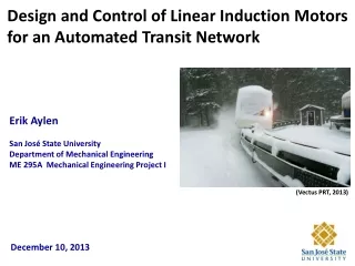
Design and Control of Linear Induction Motors for an Automated Transit Network Erik Aylen San José State University Department of Mechanical Engineering ME 295A Mechanical Engineering Project I (Vectus PRT, 2013) December 10, 2013
This presentation focuses on the use of linear induction motors for transit vehicle propulsion. Linear Induction Motors: Benefits, Design, and Construction Where We Are Now: Linear Motors in Modern Transit Systems Where We Can Be: Automated Transit Networks How It Can Be Done: Simulation and Control
Linear induction motors (LIMs) can deliver contactless linear force instead of rotational torque. (Lee, Park, et al., 2008) Secondary plate Primary windings (University of Michigan, 2011)
Linear motors offer capabilities that rotary motors cannot. (Daily Courier, 2013)
Linear motors offer capabilities that rotary motors cannot. (China Photos/Getty Images, 2008)
Linear motors can serve as effective propulsion for controlled-access transit vehicles. Short primary system: Primary coils are on the underside of the vehicle. Secondary plate runs the length of the track. (Wikimedia Commons, 2008)
The long primary system mounts the primary coils along the length of the guideway. Primary coils are stationary. Secondary is mounted on the vehicle. (International Maglevboard, 2006)
Linear motors are currently being used in many transit systems worldwide. (Hellinger and Mnich, 2010)
The technology to build a successful Automated Transit Network already exists and is being put to use worldwide. Ultra Global PRT at London Heathrow Airport (Ultra Global PRT, 2010) Vectus Suncheon Bay, South Korea 2getthere Masdar City, United Arab Emirates (Vectus PRT, 2013) (2getthere, 2013) Each implementation is site-specific. There is no one-size-fits-all solution.
An interdisciplinary group here at SJSU is designing SuperWay – an ATN for Silicon Valley.
The speed and safety performance numbers required for an ATN are achievable using LIMs. Vehicle Mass: 1100 kg Cruise Speed: 22 m/s Headway for Brick Wall Stop: 3.7 s Headway for 0.5 g Stop: 1.4 s Nominal Fore/Aft Acceleration: 1.125 m/s Force Required: 2000 N Energy Required: 450 kJ Power Required: 23 kW Emergency Stop: 3.0 m/s Force Required: 4500 N Power Required: 50 kW
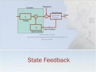
LIMs have become more viable with improvements in processing power. MATLAB / Simulink
However, LIMs have inherent drawbacks, notably much lower electrical efficiency than rotary motors. End effects cause as much as a 40% increase in steady-state current vs. rotary devices. (Motlagh, 2012) Typical values of air gap for wheeled vehicles (non-maglev) are ≥ 12mm. (Hellinger, Mnich, 2010) Larger air gap spacing and vibrational variance can reduce efficiency by 70%. The air gap of a LIM is an important indicator of vehicle transmission efficiency. (Wu et al., 2010)
Development work on this project will continue through Spring 2014. • Upcoming tasks for next semester: • Solidify my understanding of LIM thrust vs. rotary motor torque equations • Build or acquire: LIM, power electronics, small cart/bogie • OR: use full-scale SuperWay cabin • Model applicable hardware using Simulink • Develop a motor control algorithm
In summary, this project will provide guidance for the implementation of LIM propulsion in the SuperWay ATN. Hardware acquisition and testing Mathematical model and control software development Questions?