
初始化串列通訊埠
初始化串列通訊埠. 在啟始串列傳輸介面時有以下 3 個步驟:假設傳輸的通訊協定為 9600bps ,傳送 8 個位元資料,沒有同位位元, 1 個停止位元。 步驟 1 :設定 控制暫存器 SCON 以串列傳輸模式 1 做資料傳送,並將接收致能,則相對 SCON 暫存器值可以做 如下設定: SM0 SM1 SM2 REN TB8 RB8 TI RI 0 1 0 1 0 0 0 0 其值為 50H 程式為 : SCON=0X50 ;.

初始化串列通訊埠
E N D
Presentation Transcript
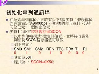
初始化串列通訊埠 • 在啟始串列傳輸介面時有以下3個步驟:假設傳輸的通訊協定為9600bps,傳送8個位元資料,沒有同位位元,1個停止位元。 • 步驟1:設定控制暫存器SCON • 以串列傳輸模式1做資料傳送,並將接收致能,則相對SCON暫存器值可以做 • 如下設定: • SM0 SM1 SM2 REN TB8 RB8 TI RI 0 1 0 1 0 0 0 0 • 其值為50H • 程式為 : SCON=0X50;
初始化串列通訊埠 • 步驟2:設定計時器1工作模式 • 規劃TMOD暫存器,使用計時器1,工作在模式2,自動重新載入計數值。 • GATE C/T M1 M0 GATE C/T M1 M0 0 0 1 0 0 0 0 0 • 其值為20H,程式為 : TMOD=0X20; • 步驟3:設定鮑率 • 為了方便鮑率的設定,將8051單板上石英振盪晶體改為22MHz,當做系統工作時脈,傳輸的鮑率為9600 bps,所以設定計時器1為重新載入250(FA),對TH1寫入計數值,而TL1可以不管。 • 程式為 : TH1=0XFA;
初始化串列通訊埠 • 步驟5:設定串列傳送中斷旗號 • 設定串列傳送中斷產生旗號, • 程式為 : TI=1; • 令特殊目的暫存器SCON的位元1(TI)變為1。 • 因此將上述的5道指令合併,可以完成8051串列埠的初始化工作。初始化副程式設計如下:
初始化串列通訊埠 init_rs232() /* 初始化 RS232 通訊介面 */ { /* 通訊協定 : <9600 N 8 1> */ /* 設定串列介面工作於模式1,接收資料致能 */ SCON=0x50; TMOD=0x20; /* 設定計時器1 工作於模式2 */ TH1 =0xFA; /* 設定鮑率為 9600 BPS */ TR1=1; /* 啟動計時器1 開始計數 */ TI=1; /* 設定串列傳送中斷產生旗號 */ }
四、燒錄程式 • 燒錄程式 • J32 1-2, 3-4, 5-6 pin 短路 • 按RESET SW
J32 RS-232串列埠單元
五、執行程式 • 燒錄程式 • J32 1-2, 3-4, 5-6 pin 短路 • 按RESET SW • 執行程式 • J32 1-2, 3-4pin 短路 • J32 5-6 pin 開路 • 按RESET SW
#include <reg51.h> char *title="rpc IO51 rx data from PC.....\r\n"; delay(int d) { int i, j; for(i=0; i<d; i++) for(j=0; j<200; j++); } init_rs232() //設定8051串列通訊組態 { SCON=0x50; TMOD=0x20; TH1 =0xFA; TR1=1; TI=1; }
tx_char(unsigned char c) { while(1) if(TI) break; TI=0; SBUF=c; } tx_str(char *str) { do { tx_char(*str++); } while(*str!='\0'); }
char rx_char() { while(1) if(RI) break; RI=0; return SBUF; } init_timer() //設定8051計時器組態 init_timer() { TR0=1; }
main() { char c; init_rs232(); while(1) { c=rx_char(); case 0x3f: tx_char(0x01); break; case 0x2b: //”+”號 tx_char(TL0); break; default: tx_char(0x00); } }
sbit wled = P3^7; delay(int d) { int i, j; for(i=0; i<d; i++) for(j=0; j<200; j++); } //P3.7閃燈 led_bl() { int i; for(i=0; i<4 ;i++) { wled=0; delay(500); wled=1; delay(500); } }
//P1向右走閃燈 led_right() { char i; unsigned char c; P1=0x00; delay(100); c=0x80; /* 1000 0000 */ for(i=0; i<8; i++) { P1=c; delay(200); c=c>>1; } } //P1向左走閃燈 led_left() { char i; unsigned char c; P1=0x00; delay(100); c=1; /* 0000 0001 */ for(i=0; i<8; i++) { P1=c; delay(200); c=c<<1; } }
main() { char c; init_rs232(); while(1) { c=rx_char(); case 0x3f: tx_char(0x01); break; case 0x2b: //”+”號 tx_char(TL0); break; case 0x2d: led_bl(); break; default: tx_char(0x00); } }