Download
1 / 78
1k likes | 1.49k Views
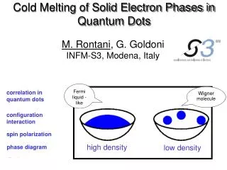
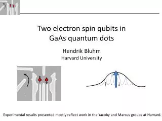
Two electron spin qubits in GaAs quantum dots Hendrik Bluhm Harvard University. Experimental results presented mostly reflect work in the Yacoby and Marcus groups at Harvard. Quantum computing – the goal. Principles of quantum mechanics Built-in parallelism

E N D
Two electron spin qubits in GaAs quantum dots Hendrik Bluhm Harvard University Experimental results presented mostly reflect work in the Yacoby and Marcus groups at Harvard.
Quantum computing – the goal • Principles of quantum mechanics • Built-in parallelism • Exponential speedup (for some problems) • Quantum bits • |0 + b |1 • N qubits: 2N dimensional Hilbert space • |0, |1, …, |2N-1 Classical bits 0 or 1 N bits => 2N states 0, 1, …, 2N-1
The case for spin qubits • Quantum computing needs two level systems • Spins natural choice • Compatible with semiconductor technology • Potential for scalability • Why not charge? • Charge couples to phonons, photons, other charges, cell phones, … • Spins are very weakly coupled to other things • e.g.: Electric vs. magnetic dipole transitions • (Reason: lack of a magnetic monopole) Now: Intel Pentium i7-980X Future: Quantum i2
Reason for weak coupling • Time reversal symmetry enforces degeneracy at B = 0(Kramer’s doublets) => no dephasing from electric fields • Matrix elements for decoherence cancel to lowest order(Van Vleck cancellation) • Decoherence times (bulk) • P- donor electrons in 28Si: T2 = 600 msTyryshkin et al., (unpublished ?) • 29Si nuclei in purified 28Si: T2 = 25 s at RT Ladd et al., PRB 71, 014401 (2005) • Problem: Single spins difficult to control
Two electron spin qubits • Idea: use two spins for one qubit • Electrically controllable exchange interaction • Tunable electric coupling • Fast, convenient manipulation • Relies on same techniques as single-spin GaAs qubits in quantum dots (Lars Schreiber) • Longest coherence time of all electricallycontrollable solid state qubits.
Outline • Lecture I • Motivation • Encoded qubits • Physical realization in double quantum dots • Principles of qubit operation • Single shot readout • Lecture II • Decoherence • Hyperfine interaction with nuclear spins • Recent progress on extending coherence
Outline Motivation Encoded qubits Physical realization in double quantum dots Principles of qubit operation Single shot readout
Requirements for qubits DiVincenzo Criteria for a viable qubit Well-defined qubit Initialization Universal gates Readout Coherence
Encoded qubits • Qubit = coherent two level system => single spin ½ most natural qubit • Any 2D subspace of a quantum system can serve as a qubit. • Advantages • + Wider choice of physical qubits • + Decoherence “free” subspace – choose states that are decoupled from certain perturbations • + Reduced control requirements – choose subspace with convenient knobs. • Caveats: • Leakage out of logical subspace can cause additional errors. • More complex control sequences. Qubit subspace
S-T0qubit using two spins Idea: Encode logical qubit in two spins All spin states: m = 0 logical subspace m = 1 • Decoherence “free” subspace (DFS) • m = 0 for both logical states • no coupling to homogeneous magnetic field • insensitive to fluctuations • Simplified operationUse exchange coupling between two spins => no need for single spin rotations. Theoretical proposal: J. Levy, PRL 89, 147902 (2002)
Bloch Sphere Mixed states are statistical mixtures of pure states and can be inside the Bloch sphere. • Any pure state of a qubit corresponds to a point on the surface of a sphere. • They can be identified with the direction of a spin ½.
Single qubit operations • Unitary transformations are rotations on the Bloch sphere • Universal quantum computing requires arbitrary rotations, which can be composed from rotations around two different axis. • Standard Rabi control • Modulate wx resonant with wz.(e.g. AC magnetic field for spins) • Changing phase of AC signal changes rotation axis in the rotating frame.
Gate operations B2 B1 DBz = B1 – B2 J 2) Exchange: => mixing between and 1) In field gradient: => and acquire relative phase DBz J
Single spin vs. S-T0 Single spin qubit Two-spin encoded qubit DBz Bz J Bx • Typically uses resonant modulation of Bx. • Bx can be an effective field (e.g. spin-orbit). Typically relies on switching of J
Two-qubit gates • Quantum computing requires (at least) one entangling gate between two (or more) qubits (cNOT, cPHASE, ). • Single spins:p/2 exchange provides • Encoded qubits: construct gates from several steps. • S-T0: Construction of nAND gate, equivalent to cNOT, cPHASE • In practice, can also use Coulomb interaction to implement cPHASE gate directly. J
nAND gate for S-T0qubit Evolve in field gradient (p/2) Evolve in field gradient (p/2) SWAP inner spins (exchange) SWAP inner spins Spin 1A B1 B1 Qubit A Spin 1B B2 B2 Spin B1 B1 B1 Qubit B Spin B2 B2 B2 Principle of operation: Acquires phase Acquire phase No phase acquired Outside logical subspace! Return to subspace Initial state
Exchange-only with three spins ½ Idea: use m = ½ subspace. Single qubit: 4 steps J1(t) J1(t) J2(t) J2(t) Two qubit: 27 steps • No magnetic field required. • Uses only exchange. • DiVincenzo et al. Nature 408, p. 339 (2000) • Experimental status: Suitable samples developed, but no coherent control yet. (Gaudreau et al. arxiv)
Tradeoffs summary Encoding a qubit in several spins reduces control requirements at the expense of complexity. (experimentally most difficult step in red)
Outline • Motivation • Encoded qubits • Physical realization in double quantum dots • Principles of qubit operation • Theory of operation • Experimental procedures • Single shot readout
2D-electron gas (2DEG) GaAsheterostructure conduction band edge Wafer surface Dopants induceelectric field Step at material interface Electrons in triangular confining potential occupy lowest subband. • Structure grown layer by layer with Molecular Beam Epitaxy (MBE) • Atomically smooth transitions • Ultra-high purity
Device fabrication Fabrication - + Negative gate voltage pushes electrons away. Goal:trap two electrons 2DEG Metal gate 500 nm • + • V Graphics: Thesis L. Willems van Beveren, TU Delft
Understanding a complex system Metal gates - + Si doping 90 nm + + + + + + + + + + + + Al0.3Ga0.7As Dopants, defects and impurities cause disorder 2D electron gas (Fermi-sea) Individual confined electrons GaAs Electrostatic potential from gates Conduction band edge First realization and overview of experimental toolbox: Petta et al., Science 309, p. 2180 (2005)
Charge control E (1, 1) (0, 2) S(0, 2) 2DEG T-(1, 1) V(x) T0(1, 1) T+(1, 1) Metal gate 500 nm x S(1, 1) S(0, 2) • + • -V • + • +V e 0 • + • V0 e = E(1, 1)-E(0, 2) V -V +V e < 0 e > 0
Charge control E (1, 1) (0, 2) V(x) (1, 1) 500 nm x (0, 2) • + • V • + • V e 0 (1, 1) (0, 2) e = E(1, 1)-E(0, 2) V -V +V e < 0 e > 0
Singlet-Triplet splitting in (0,2) First excited state 0 E T(0, 2) (1, 1) S-T splitt. S(0, 2) Ground state 0 e 0 • (0, 2) states: • Spin singlet: (x1, x2) = 0(x1) 0(x2)|S> • Spin triplet: • (x1, x2) = (0(x1) 1(x2)-0(x2) 1(x1))|T> • (0, 2) Triplet has higher energy than (0, 2) Singlet. (1, 1) T(0, 2) S(0, 2)
Tunnel coupling E E S(0, 2) Tunnel coupling T(1, 1) T(0, 2) tunnel coupl. J(e) S(1, 1) S(0, 2) T(1, 1) S(0, 2) S(1, 1) e e 0 0 • Tunnel coupling • Avoided crossing for singlet • Triplet crossing at larger e can be ignored. • Conveniently described in terms of J(e) T S ->
Zeeman splitting E S(0, 2) T-(1, 1) m = 0 T0(1, 1) T+(1, 1) Ez = gmBBext m = 1 m = -1 S(1, 1) S(0, 2) e 0 Bz ~ 10 mT to 1 T
Qubit states E S(0, 2) T-(1, 1) T0(1, 1) tunnel coupl. T+(1, 1) Ez = gmBBext S(1, 1) S(0, 2) e 0
Qubit dynamics with field gradients E S(0, 2) T-(1, 1) T0(1, 1) T+(1, 1) Transitions between S and T+ driven by DB. J(e) S(1, 1) S(0, 2) e 0 DBz • << 0: Free precession e~< 0: Coherent exchange BextBz/2 J
Effective Hamiltonians T0 S In logical subspace: S T+ T- T0 All spin states: H = Coish and Loss, PRB 72, 125337
Outline • Motivation • Encoded qubits • Physical realization in double quantum dots • Principles of qubit operation • Theory of operation • Experimental procedures • Single shot readout
Isolating two electrons # electrons in each dot V(x) G (1, 0) Gqpc (nL, nR)=(1, 1) VL x Gqpc • + • VL • + • VR (0, 0) (0, 2) (0, 1) 10 mV Conductance depends on electric field from electrons VR (1, 1) (0, 2) 2 mV (1, 2) (1, 1) VL (0, 2) (0, 1) VL VR VL VR Gqpc VR
Tuning the tunnel coupling Measure current through double dot VSD =0.4 mV I Gqpc VL 2 mV 0 10 20 • + • VL • + • VR Gqpc VGateR VL (1, 2) Magnitude and variation of current and charge signal reveal tunnel couplings. Target: tc ~ 20 meV Tunneling rate to leads ~ 100 MHz (1, 1) 2 mV VL VGateR Isd(pA) (0, 2) (0, 1) VR
Pulsed Measurements V(x) x Gqpc 1 ns gate control S (1, 1) Typical pulse cycle for qubit operation Initialize S at reload point R. Manipulate (nearly) separated electrons (S) Return to M for measurement. (1, 1) (0, 2) M (0, 2) R Q
Readout E S(0, 2) • Goal: distinguish S and T state of separated electrons. • Mechanism: • Increase e. • (1, 1)S adiabatically transitions to (0, 2). • T stays in (1, 1) (metastable). • Life time long enough to detect charge signal. T-(1, 1) T0(1, 1) T+(1, 1) S(1, 1) X S(0, 2) e 0 T0 S Johnson et al., Nature 435, p. 925 (2005) Q Q
Readout region and Initialization E S(0, 2) T-(1, 1) T0(1, 1) (1, 1) T+(1, 1) Region in which (1, 1)T is long lived (Spin Blockade) e S(0, 2) Gqpc S(1, 1) (0, 2) • Initialization of S at reload point R after • a measurement: • If in (0, 2)S, nothing happens. • (1, 1)T -> (0, 1) -> (0, 2)S via exchange with leads. • Duration ~ 100 ns. • - High fidelity due to large S-T splitting S e (1, 1) Outside blocked region, (1, 1) can decay to lead. 0 M (0, 2) R
Outline Motivation Encoded qubits Physical realization in double quantum dots Principles of qubit operation Single shot readout
Single shot readout • For many experiments, can average signal over many pulses. • No high readout bandwidth required. • Reduce noise by long averaging. • => Can use standard low-freq lock-in measurement with room-temperature amplification to measure GQPC.Minimum averaging: 30 ms, 3000 pulses. • Single shot readout • Determine qubit state after each single pulse with high fidelity. • Benefits and applications: • Quantum error correction. • Verify entanglement through correlations and Bell inequalities. • Fundamental studies (e.g. projective measurement) • Fast and accurate data acquisition.
RF-reflectometry Demodulation Goal: increase bandwidth and sensitivity ofcharge readout with RF lock-in technique. Reilly et al., APL 91, 162101 (2007) Low noise cryogenic amplifier Excitation Reflected signal RF components 50 W, sensor 50 kW=> Impedance matching with LC resonator.
Single shot readout Sensor signal Histogram of cycle-averages Reinitialization and manipulation of qubit => random new state Averaging window (ms scale) • Each peak corresponds to one qubit state. • Broadening due to (amplifier) readout noise. Need to distinguish state before the metastable triplet can decay (ms scale). Barthel et al., PRL 103 160503 (2009)
Improvement with quantum dot sensor Quantum point contact Qubit state modulates single tunnel barrier. Quantum dot (single electron transistor) Modulation of ability to add electron to island Quantum dot Factor 3 increase in sensitivity=> factor 10 reduction in averaging time. QPC Peaks need to be well separated to distinguish states. Barthel et al., PRB 81 161308(R), 2010
Readout summary • Qubit is read out by spin-to-charge conversion utilizing spin blockade. • State is read using a charge sensor before the metastable (1, 1)T decays. • RF reflectometry allows single shot readout • Fidelity > 90 % X T0 S Q Q
Measuring coherent exchange Exchange pulse e E initialize evolve readout (0, 2) T0(1, 1) (gate voltage) (1, 1) t J(e) t Petta et al., Science 2005 S(1, 1) S(0, 2) e J Decay reflects dephasing due to electric noise.
Exchange echo e initialize evolve readout (0, 2) (gate voltage) (1, 1) t/2 + Dt t/2 t p p DBz- rotation DBz Echo signal J T2 = 1.6 ms t = 2 ms
Coherence times x CPMG Hahn-echo All data fitted with ~1 nV/Hz1/2 white noise with 3 MHz cutoff. Consistent with expected Johnson noise in DC wires => improvement with filtering.
Outline • Lecture I • Conceptual and theoretical background • Physical realization and principles of qubit operation • Single shot readout • Lecture II • Decoherence • Hyperfine interaction with nuclear spins • Recent progress on extending coherence
Main results • Used qubit as quantum feedback loop to suppress nuclear fluctuations and enhance T2*. • Detailed picture of bath dynamics and decoherence from echo experiments. • T2 200 ms achieved with quantum decoupling. • Universal control.
Outline • Background • Error correction • Decoherence • Hyperfine interaction • Measuring and manipulating the nuclear hyperfine field • Universal control • Reduction of nuclear fluctuations via 1-qubit feedback loop • Coherence with echo and dynamic decoupling
Decoherence vs. control – the challenge • Qubits are analog => small errors matter • Using phase => Uncertainty relation forbids any leakage of information • However: • Need to manipulate qubit • Qubits have to interact • Eventually want to measure qubit • need extremely tight control over interactions. • Impossible? – not quite. “Only” need ~102 - 106 coherent operations per error with quantum error correction.
Threshold theorem • Small enough error probability per gate operation • => error correction can make QC fault tolerant without exponential overhead. • Basic idea: • Encode logical qubits redundantly in several physical qubits, e.g. |1L = |111, |0L = |000. • Can detect errors that leave the logical subspace => encoded information is not extracted. • Correct errors if detected. • Hurdle: Error correction operations will be subject to errors themselves. • Solution: • (Error probability) x #(physical gate operations per logical gate) < 1=> reduce error by hierarchically concatenating error correction codes (i.e. using the logical qubits of on level as the physical qubits of the next higher level).