Download
1 / 27
280 likes | 563 Views
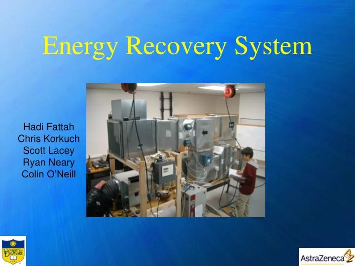
Energy Recovery System. Hadi Fattah Chris Korkuch Scott Lacey Ryan Neary Colin O’Neill. Overview. Project Scope Benchmarking Concept Choice Concept Description Detailed Design Manufacturing and Assembly Prototype Components Operation and Testing Results Analysis Cost of Prototype

E N D
Energy Recovery System Hadi Fattah Chris Korkuch Scott Lacey Ryan Neary Colin O’Neill
Overview • Project Scope • Benchmarking • Concept Choice • Concept Description • Detailed Design • Manufacturing and Assembly • Prototype Components • Operation and Testing • Results • Analysis • Cost of Prototype • Cost Savings for Sponsor • Conclusion
Project Scope • ASHRAE prohibits the recirculation of air in chemistry labs • Large amounts of energy are lost • Large amounts of money is spent on HVAC • Any amount of energy recovered would provide substantial savings • Our objective is to find a way to recover energy within ASHRAE standards
Benchmarking • Heat pipe • Heat transfer via evaporation, condensation of fluid that moves by negative pressure, gravity and capillary action • No contamination occurs between flows, and the system tends to be 45% - 65% effectiveness. • Run-around coil • Indirect heat exchanger of sensible energy between two fluid streams • Effectiveness: 55 to 65%
Benchmarking • Enthalpy Wheel • This system consists of a rotary heat exchanger involving the transfer of sensible and latent heat • Small amount of contamination may occur into inlet air stream, but fulfills ASHRAE requirements. • 75% effectiveness (highest among its competitors). http://www.ice-us.com/CustomSeries-Product.htm
Why Enthalpy Wheels? • Enthalpy Wheels offer the most efficiency through the simultaneous transfer of latent and sensible energy • Heat Pipes and Run around coils do not transfer latent heat
How an Enthalpy Wheel Works Cooling Mode (Summer) http://labs21.lbl.gov/DPM/Assets/a3_fischer.pdf
How an Enthalpy Wheel Works Heating Mode (Winter) http://labs21.lbl.gov/DPM/Assets/a3_fischer.pdf
Heater • 8kW of power • Temperature range 30-75 degrees @ 850 cfm • Powered by three phase 208V, 30A rated socket • 0-10V controller for 10 • levels of heating (0=off, • 10=max) • Pitot tube ensures • minimum flow rate to • prevent burn-up
Humidifier • 8lb/hour steam humidification • Shares three phase 208V, 20A rated socket with fan • Linked with control panel for automatic humidity regulation. • Steam outlet faces against airflow to maximize effectiveness.
Enthalpy Wheel • AirXchange Inc. Model ERC-25 Enthalpy Wheel • Provides latent and sensible energy recovery • Provides low cross-contamination between flows (<0.04%) • Coated with silica gel for performance • Rotates using small electric motor running of regular 120V socket
Fan • Capable of 2200 cfm flow rate • Controlled by 0 to 60Hz VFD • Shares three phase 208V, 20A rated socket with humidifier
Temperature/Humidity Sensors • 0-10V output for temperature and humidity scaled for 0%-100% RH and 0 – 100 degrees temperature scale • Linked to control panel for active readings • Installed on inlet and exhaust of enthalpy wheel for both streams
Flow Rate Meter • Mounted (2) sensors in 14” section of metal duct before fan • Average flow rate between two sensors outputs to control panel • Volume dampers in both streams also installed to even flows by reducing flow area (if needed).
Control Panel • Powered by regular 120V socket • Reads temperature, humidity, and flow rates • Linked to dehumidifier for automatic humidity control
Cost of prototype • Equipment:$13032 • Labor: $434 • Subcontractors:$4955 • Miscellaneous: $115
AstraZeneca Cost Savings • Winter (3 months) • Boiler creates steam to heat air • Boiler runs off Natural Gas at $5.40/MMBtu • 1 month of operation saves: $111,856 • Summer (3 months) • Chiller cools water to cool air • Chiller runs off electricity at $41.40/MWh • Estimated yearly savings: $1,125,681
Conclusion • Through benchmarking and research, the best concept involved use of an Enthalpy wheel • After designing the system in collaboration with MDavis & Energy Transfer Solutions, the prototype was built • Experimentation supports expected results of efficiency • Cost savings are significant, and the payback period is well within industry standards at 0-2 years.
Acknowledgements • Special thanks to John Sorantino and Joe from MDavis & Sons, Mike Haggarty and Dave from Energy Transfer Solutions – without them prototype fabrication would not be possible • Thanks to Professor Hartman for all the help and guidance • Finally, and most importantly, Thank You to George Sestak and AstraZeneca – for their generous support and for this opportunity.