Download
1 / 30
300 likes | 336 Views
Explore the cutting-edge diagnostic radiology technologies at Gyeongsang National University Hospital Department, including Direct Radiography (DR) systems and Computed Radiography (CR) innovations. Learn about detector technologies, economic considerations, and the evolution of digital radiography in the medical field. Discover the future of radiological imaging technology.

E N D
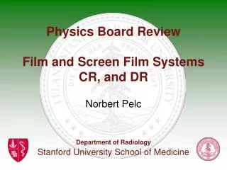
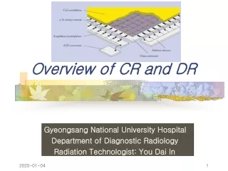
Overview of CR and DR Gyeongsang National University Hospital Department of Diagnostic Radiology Radiation Technologist: You Dai In
Direct Radiography (DR) • Overview of DR systems CCD based systems TFT + Phosphor TFT + Photoconductor
Detector technology:CCD based systems A. Lens Coupling B. Fiber optic coupling C. multiple detectors A phosphor screen converts X-rays into visual light that is projected onto a CCD or onto a CCD-array
CCD based systems • Mature technology • Mostly dedicated applications: mammography, chest • FDA approved except for mammography
Detector technology:TFT + Phosphor Phosphor screen converts X-ray photons into visual photons. Phosphor Photodiode converts visual photons into electrons Electrons are stored on capacity of switching element
TFT + Phosphor • GOS systems: available on the market • CsI systems: limited availability • FDA approved
Detector technology:TFT + Photoconductor Charge transport in photoconductor Electrons migrate to surface electrode Electrons are stored on capacity of switching element
TFT + Photoconductor Experimental except Hologics
Weaknesses of TFT systems • Low yield of TFT array fabrication • Ghost images • Charge trapping in amorphous semiconductors • Clustering of Tl+ dopant in CsI needles • Limited dynamic range (a- Se) due to high dark current • Image deformation beyond w>Nyquist due to aliassing (a-Se) • Electronic noise in low dose applications • Detector damage at high dose (capacitoroverload)
I I 0 I I 00 I I 00 I 00 I 0 I 0 I I I Principle of CR Galvanometer Photomultiplier Electrical Signal Laser Light guide A/D Storage phosphor plate Digitisation Rollers
Computed Radiography • Mature and robust technology • FDA approved and clinically accepted for all applications except mammography
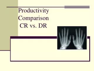
Flat Panel Investment $250-300K forone room $100K to replace damaged detectorDR 20% higher productivity 6 pat./h x 2exp./pat. x 10h/day x 200 days/yr = 24 000 exp/yr 1 room = 24 000 exp./yr Amortisation 5 yrs = 120 000 exp. $350 000 / 120 000 exp. = $2.90/exp. CR Investment $150K for 3 to 4 rooms $1K to replace damaged detectorCR productivity ~conventional 5 pat./h x 2exp./pat. x 10h/day x 200 days/yr = 20 000 exp/yr 3 rooms = 60 000 exp./yr Amortisation 5 yrs = 300 000 exp. $150 000 / 300 000 exp. = $0.50/exp. CR and DR: Economics
Assumptions • Penetration of digital acquisition in the x ray rooms will evolve from 2.5% in 1999 to 11% in 2005 • Within this digital segment, DR will substitute CR differently according to the application: • Mobile: 100% retention of CR by 2005 • Chest: 0% retention of CR • General Rad high end: 70% retention of CR • General Rad low end: 85% retention of CR
CR and DR New flat panel digital detectors are compact, offer fast image acquisition and promise excellent image quality CR DR Flat panel
Innovation in Plate technology • more absorption • higher sharpness • higher image quality “state of the art CR” Powder Phosphor BaFBr Needle Phosphor CsBr
New CsBr:Eu PhosphorHigher image quality • Cubic crystal facilitates needle growth • Equivalent specific X-ray absorption: ( =4.44 vs. 5.1 g/cm3) • Efficient stimulation with diode laser (stimulation 685 nm) • Efficient detection with PMT or CCD (emission 450 nm) • Excellent storage phosphor: • Conversion efficiency > BaFBr:Eu (more light / absorbed X-ray) • Lower stimulation energy Read-out requires 3 times less laser power
Galvo Collimator Laser Light Beam Scan-Head SHT Phosphor Image Plate Fiber Optic Phosphor ImagePlate Photo Detector Scanhead line scanner:Higher throughput Flying Spot Scanhead Scan: pixel per pixel Scan: line per line Detector: Photomultiplier Detector: CCD Fast acquisition (5s scan, 20s cycle) QE CCD > QE PMT Higher gain
Scanhead - Scanning Principles CCD Sensor Laser Diode Array CCD Sensor Optics Optics Image Plate Image Plate Laser Diode Array Front-Stimulation ADC Stratus Back-Stimulation CR Panel
CR Scanhead, the unifying technology (DR) Scanhead • simple • mature • robust • economic • multi-application Phosphor Image Plate • fast • compact • integrated • higher image quality AGFA - Patent
Conclusions • The different technologies will coexist • Best choice will depend on application • CR potential is promising • The difference between CR and DR technology will become less relevant