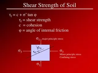
5.8 SHEAR STRENGTH
540 likes | 839 Views
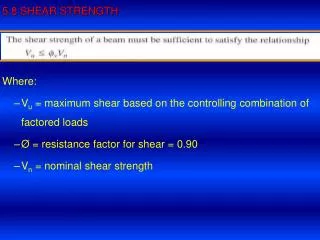
5.8 SHEAR STRENGTH. Where: V u = maximum shear based on the controlling combination of factored loads Ø = resistance factor for shear = 0.90 V n = nominal shear strength.

5.8 SHEAR STRENGTH
E N D
Presentation Transcript
5.8 SHEAR STRENGTH Where: Vu = maximum shear based on the controlling combination of factored loads Ø = resistance factor for shear = 0.90 Vn = nominal shear strength
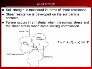
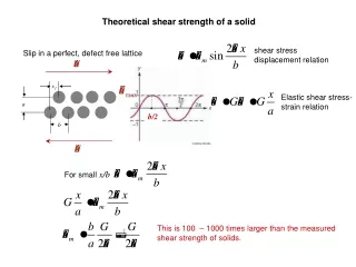
Consider a simple beam as shown in Fig. a. At a distance x from the left end and at the neutral axis of the cross section, the state of stress is as shown in Fig. d. Because this element is located at the neutral axis, it is not subjected to flexural stress.
From elementary mechanics of materials, the shearing stress is This equation based on the assumption that the stress is constant across the width b, and it is therefore accurate only for small values of b, so the equation can not be applied to the flange of a W shape in the same manner as for the web.
The following Figure shows the shearing stress distribution for a W-shape. The average stress in the web w is V/ Aw No big difference between the average stress and the maximum stress The web will completely yield long before the flanges begin to yield.
We can write the equation for the stress in the web at failure as: Where Aw is the area of the web. The nominal strength corresponding to this limit state is therefore The relationship between shear strength and the width-thickness ratio is analogous to that between flexural strength and the width thickness ratio (for FLB or WLB) and between flexural strength and unbraced length (for LTB)
Where, Aw is the area of the web = d*tw And d is the overall depth of the web. If h/twis greater than 260, web stiffeners are required. Shear is rarely a problem in rolled steel beams; the usual practice is to design a beam for flexure and then to check it for shear.
Example 5.7 Check the beam in Example 5.6 for shear. Solution: From Example 56: A W14X90 with Fy = 50 ksi is used. Wu = 2.080 kips/ft and L= 40 ft From the Manual
The strength is governed by shear yielding of the web The shear design strength is greater than the factored load shear, so the beam is satisfactory.
BLOCK SHEAR To facilitate the connection of beams to other beams so that the top flanges are at the same elevation, a short length of the top flange of one of the beams may be cut away, or coped. If a coped beam is connected with bolts as in Figure, segment ABC will tend to tear out. The applied load in this case will be the vertical beam reaction. Shear will occur along line AB and there will be tension along BC. Thus the block shear strength will be a limiting value of the reaction.
We covered the computation of block shear strength in Chapter3
5.9 Deflection Steel beams are designed for the factored design loads. The moment capacity, i.e., the factored moment strength (φbMn) should be greater than the moment (Mu) caused by the factored loads. A serviceable structure is one that performs satisfactorily, not causing discomfort or perceptions of unsafety for the occupants or users of the structure. For a beam, being serviceable usually means that the deformations, primarily the vertical sag, or deflection, must be limited. The maximum deflection of the designed beam is checked at the service-level loads. The deflection due to service-level loads must be less than the specified values. Appropriate limits for deflection can be found from the governing building code.
For the common case of a simply supported, uniformly loaded beam such as that in the following Figure, the maximum vertical deflection is: Deflection limit:
Example 5-9 : solution
Ponding is one deflection problem that does affect the safety of a structure. The AISC specification requires that the roof system have sufficient stiffness to prevent ponding.
5.10 DESIGN: • Beam design entails the selection of a cross-sectional shape that will have enough strength and that will meet serviceability requirements. • The design process can be outlined as follows: • Compute the factored load moment. • Select a shape that satisfies this strength requirement. This can be done in one of two ways: • Assume a shape, compute the design strength, and compare it with the factored load moment. • Use beam design chart in part 5 at Manual (preferred). • Check the shear strength. • Check the defection.
Beam Design Charts: • Many graphs, charts, and tables are available for the practicing engineer, and these aids can greatly simplify the design process. • To determine the efficiency, they are used in design offices. • You should approach their use with caution and not allow basic principles to become obscured. • The curves of design moment versus un braced length given in Part 5 of the Manual. • All curves were generated with Fy =50 ksi and Cb = 1.0. • For other values of Cb simply multiply the design moment from the chart by Cb.
The following curve described the design moment ФbMn as a function of unbraced length Lb for a particular compact shape.
Remember that design strength can never exceed plastic moment Noncompact shapes may fail due to local buckling Two sets of curves are available, one for W-shapes and one for C-shapes and MC-shapes.
Example 5.12 Use A992 steel and select a rolled shape for the beam shown below. The concentrated load is a service live load, and the uniform load is 30% dead load and 70% live load. Lateral bracing is provided at the ends and at mid span. There is no restriction on deflection.
5.12 HOLES IN BEAMSIf beam connections are made with bolts, holes will be punched or drilled in the beam web or flange.Sometimes electrical conduits and ventilation ducts need large holes.Ideally, holes should be placed in the web only at section of low shear, and holes should be made in the flanges at points of low bending moment.This is not always be possible, so the effect of the holes must be accounted for.The effect of small holes will be small, particularly for flexure.
AISC B10 permits bolt holes in flanges to be ignored when: 0.75 FuAfn ≥ 0.90 FyAfg where, Afgis the gross tension flange area and, Afnis the net tension flange area. If this condition is not met, the previous equation is solved for an effective tension flange area that satisfies that criterion. See examples 5.14 and 5.15
5.13 OPEN-WEB STEEL JOISTSOpen-web steel joists are prefabricated trusses of the type shown in the Figure.They are used in floor and roof systems.For a given span, it is lighter in weight and its more easier for electrical conduits and ventilation ducts than a rolled shape .More economical than a rolled shape
5.14 Bearing plates and column base plates : • The function of the plate is to distribute a concentrated load to the supporting material • Two types of beam bearing plates are considered • One that transmits the beam reaction to a support • One that transmits a load to the top flange of a beam.
The design of the bearing plate consists of three steps. • Determine dimension N so that web yielding and web crippling are prevented • Determine Dimension B so that the area N ×B is sufficient to prevent the supporting material from being crushed in bearing. • Determine the thickness t so that the plate has sufficient bending strength.
Web Yielding Web yielding is the compressive crushing of a beam web caused by a force acting on the flange directly above or below the web When the load is transmitted through a plate, web yielding is assumed to take place on the nearest section of width tw. In rolled shape, this section will be at the toe of the fillet, a distance k from the outside face of the flange If the load is assumed to distribute itself at a slop of 1:2.5 as shown
The area at the support subject to yielding is (2.5k + N) tw The nominal strength for web yielding at the support is: The bearing length N at the support should not be less than k. At the interior load, the length of the section subject to yielding is The design strength is ØRw where Ø = 1.0
Concrete Bearing Strength Usually, concrete used as the material beam support. This material must resist the bearing load applied by steel plate If the plate covers the full area of the support, The nominal strength is: If the plate does not cover the full area of the support Where fc is the compressive strength of concrete after 28 days A1 is the bearing area A2 is the full area of the support
If area A2 is not concentric with A1, then A2 should be taken as the largest concentric area that is geometrically similar to A1, as illustrated in the following Figure AISC also requires The design bearing strength is ФcPp where Фc=0.60
Plate Thickness Where Ru is the support reaction B is width of the bearing plate N is length of the bearing plate
Example 5.17 Design a bearing plate to distribute the reaction of a W 21 x 68 with a span length of 15 ft 10 inches center to center of supports. The total service load, including the beam weight , is 19 kips with equal parte dead and live load. The beam is to be supported on reinforced concrete wall with fc = 3500 psi. the beam made of A992 steel and the plate is A36. Solution The factored load is = 1.2*4.5 + 1.6*4.5 = 12.600 kips/ft The reaction is = 12.6*15.83/2 = 99.3 kips Determine the length of bearing N required to prevent web yielding. Ru = 2.5k + N) Fytw= (2.5(1.438) + N) 50*0.430 ≥ 99.73 N ≥ 1.044
Determine the length of bearing N required to prevent web crippling. Assume N/d > 0.2 N ≥ 3.0 in Check the assumption N/d = 3.0/21.1 = 0.14 < 0.2 (N.G.) so for N/d < 0.2 N ≥ 2.59 in, and N/d = 2.59/21.1 = 0.12< 0.2 (OK)
Try N = 6.0 Assume full area of support is used, the required plate area is A = Ф * 0.85 * fc * A ≥ Ru A = 0.60 * 0.85 * 3.5 * A ≥ 99.73 A ≥ 55.87 in2 B = 55.87/6 = 9.31 in The flange width of a W21x68 is 8.27 < 9.31, use B as 10 in Compute the required plate thickness, n = (B – 2k)/2 = (10 – 2*1.19)/2 = 3.81 in Use a PL 1.25 * 6 * 10.
Column Base Plates Major differences between bearing and base plates are: Bending in bearing plates in one direction, whereas column base plates are subjected to two-way bending. Web crippling and web yielding are not factors in column base plate design. Design steps: Determine the allowable strength of the foundation Determine the required column base plate area Select column base plate dimension (not less than column dimension)
Determine the thickness Where, Pp = nominal bearing strength from AISC equation
Example 5.18 A W 10 x 49 is used as a column and is supported by a concrete pier as shown in the Figure. The top surface of pier is 18 in by 18 in. Design an A36 base plate for a column dead load of 98 kips and a live load of 145 kips the concrete strength is fc = 3000 psi.