DE2-115 Control Panel - Part I
230 likes | 519 Views
DE2-115 Control Panel - Part I. 數位電路實驗 TA: 吳柏辰. Author: Trumen. Outline. Introduction to DE2-115 Control Panel Control Panel Setup Controlling the LEDs, 7-segment Displays, and LCD Display Switches and Push-buttons. Introduction to DE2-115 Control Panel. Introduction to Control Panel.

DE2-115 Control Panel - Part I
E N D
Presentation Transcript
DE2-115 Control Panel - Part I 數位電路實驗 TA: 吳柏辰 Author: Trumen
Outline • Introduction to DE2-115 Control Panel • Control Panel Setup • Controlling the LEDs, 7-segment Displays, and LCD Display • Switches and Push-buttons
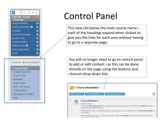
Introduction to Control Panel • The DE2-115 board comes with a Control Panel facility that allows users to access various components on the board from a host computer. • The host computer communicates with the board through a USB connection. • The facility can be used to verify the functionality of components on the board or be used as a debug tool while developing RTL code.
Control Panel Setup • The Control Panel Software Utility is located in "/DE2_115_tools/DE2_115_control_panel/" in the DE2-115 System CD. • It's free of installation, just copy the whole folder to your host computer and launch the control panel by executing the "DE2_115_ControlPanel.exe".
Activate the Control Panel (1/2) • Make sure Quartus II 10.0 or later version is installed successfully on your PC. • Set the RUN/PROG switch to the RUN position. • Connect the supplied USB cable to the USB Blaster port, connect the 12V power supply, and turn the power switch ON. • Start DE2_115_ControlPanel.exe on the host computer. The Control Panel user interface will appear.
Activate the Control Panel (2/2) • The DE2_115_ControlPanel.sof bit stream is loaded automatically as soon as the DE2_115_control_panel.exe is launched. • In case the connection is disconnected, click on CONNECT where the .sof will be re-loaded onto the board. • Note, the Control Panel will occupy the USB port until you close that port; you cannot use Quartus II to download a configuration file into the FPGA until the USB port is closed.
DE2-115 Control Panel Concept Active on the host computer Implemented in the FPGA board
Push-buttons • Each of these buttons is debounced using a Schmitt Trigger circuit. • Since the push-buttons are debounced, they are appropriate for using as reset inputs in a circuit.
Debounce Logic Circuit • Level-sensitivev.s. edge-sensitive button input(bi) Level-sensitive Edge-sensitive bi==1 bi==0 bi==0 bi==0 0 1 2 3 button state (bs) bi==1 bi==0 bi==1 bi==1 bi==1 4 6 5 7 bi==0
Switches • Switches are not debounced, and are assumed for use as level-sensitive data inputs to a circuit.
The End. Any question?
Reference • "DE2-115 User Manual" by Terasic Technologies Inc.