Download
1 / 1
20 likes | 173 Views
Omni wedge study on elekta precise digital accelerator Srinidhi G chandraguthi, B.Ramya, Jefy Ninan, Jyothi Nagesh , Susan Rochelle, Donald J Fernandes. Introduction.

E N D
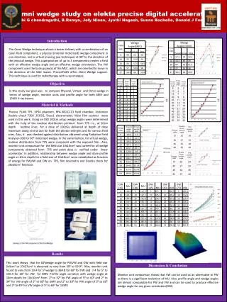
Omni wedge study on elekta precise digital acceleratorSrinidhi G chandraguthi, B.Ramya, Jefy Ninan, JyothiNagesh, Susan Rochelle, Donald J Fernandes Introduction • The Omni Wedge technique allows a beam delivery with a combination of an open field component, a physical (internal motorized) wedge component in one direction, and a virtual (moving jaw technique) at 900 to the direction of the physical wedge. This superposition of up to 3 components creates a field with an effective wedge angle and an effective wedge orientation. The VW component uses the backup jaw(s) of the MLC, which are oriented to move in the direction of the MLC leaves. PrecisePLAN offers Omni Wedge support. This technique is used for radiotherapy with x-ray energies. PW –VW-OW ANGLE COMPARISON Objective • In this study our goal was to compare Physical, Virtual and Omni wedge in terms of wedge angle, monitor units and profile angle for both 6MV and 15MV X-ray beams. Material & Methods Precise PLAN TPS ,SP34 phantom, RFA-300,CC13 field chamber, Victoreen Double check 7200 ,FC65G, Dose1 electrometer, Vidar film scanner were used in this work. Using an SSD 100cm setup wedge angles were determined with the help of the isodose distribution printout from TPS i e., at 10cm depth isodose lines for a dose of 100cGy delivered at depth of dose maximum along central axis for both the photon energies and for various field sizes. Also, it was checked against distribution obtained using Radiation Field Analyser-300 for 600 motorized wedge. In the same fashion, for virtual wedge, isodose distribution from TPS were compared with the exposed film.. Also, monitor unit comparison for the field size 10x10cm2 was carried for all wedge components obtained from TPS and point dose is verified under linear accelerator. In addition, relationship between wedge angle and dose profile angle at 10cm depth for a field size of 10x10cm2 were established as function of energy for PW,VW and OW on TPS, film dosimetry and Double check for 20x20cm2 field size. WEDGE ANGLE V/S MU(PW&VW) Pw angle v/s isodose angle OW(ORIENTATION) V/S MU Delivery of the VW component of the OmniWedge Results This work shows that for 600wedge angle for PW,VW and OW with field size 5x5cm2 to 27x27cm2 is observed to vary from 500 to 59.90 . Also, monitor unit found to vary from 19.4 for 50 wedge to 384.8 for 600 for PW and 7.4 for 50 to 150.4 for 600 for VW for 6MV. Profile angle variation with wedge angle at 10cm depth for 10x10cm2 from 20 to 320 for PW angle of 50 to 600 and 20 to 340 for VW angle of 50 to 600 for 6MV and 20 to 390 for PW angle of 50 to 600 and 20 to 400 for VW angle of 50 to 600 for 15MV. Discussion & Conclusion Monitor unit comparison shows that VW can be used as an alternative to PW as there is a significant reduction of MU. Also, profile angle and wedge angles are almost comparable for PW and VW and can be used to produce effective wedge angle for any given orientation(OW).


