Robust Position Sensing System for Caterpillar's D8 Tractor
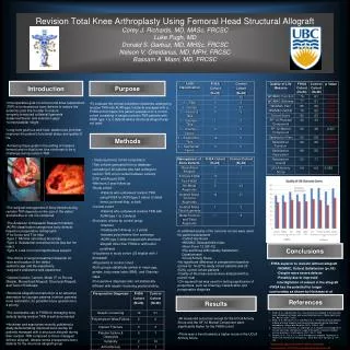
This project developed a new end implement position sensing system for Caterpillar's D8 tractor, aiming to maintain accuracy and robustness while reducing costs and repair downtime. The system consists of wheels and encoders for measuring linear displacement and a blade measurement system with rotating lasers. The design ensures accuracy and reliability, reducing maintenance costs and warranty payouts. It includes a wheel and encoder design theory, slip analysis, testing using Neato LDS system, motor control algorithms, and end blade location tracking. The project involved research, brainstorming, design selection, and testing stages to identify the best solutions for Caterpillar's needs.

Robust Position Sensing System for Caterpillar's D8 Tractor
E N D
Presentation Transcript
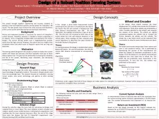
Design of a Robust Position Sensing System Y (to sky) Andrew Aubry1 ▪ Christopher Costello1▪ Phillip Latka2▪ Ken Ratekin1▪ Scott Roth3▪ Kinzie Sellers4▪ Leann Vernon2▪ Rose Wurster4 P11 Dr. Martin Morris1 ▪ Dr. Jose Sanchez2 ▪ Nick Schmidt2▪ Ken Klotz4 θT φc P12 d12 BH 1Department of Mechanical Engineering ▪ 2Department of Electrical Engineering ▪ 3Department of Finance ▪ 4Department of Marketing d11 P21 d21 Design Process P22 Project Overview d22 Design Concepts Θ22 Business Analysis X (to blade) Wheel and Encoder In this design, three wheels measure the linear displacement of a cylinder that controls the lift tractor’s end implement. These three wheels are protected by a collar. Encoders attached to the wheel’s axel measure the rotation of the wheels. The wheels are slightly compressed against the cylinder rod to increase the friction between the wheels and the cylinder. The design has a two halves which can be separated from one another to allow for easier maintenance and repair. LDS • In this design,a direct blade measurement system consisting of two LDSunits is mounted onto the side of the tractor. The LDS unitcontains a rotating laser that takes distance measurements over 360◦. For this application, the readings are limited to a span of -45◦ to +45◦. The LDS units are mounted on both sides of the tractor where the units will measure distances in the vertical plane. These readings are then analyzed using several algorithms to determine the exact location of the blade relative to the ground. Objective This project brought together engineering and business students to develop a new end implement position sensing system for Caterpillar’s D8 tractor. The new system must maintain the same accuracy and robustness of the current system while decreasing cost and repair downtimes. Background Precise end implement position is necessary for several of Caterpillar’s current features. Therefore, precision is needed to remain competitive in an industry that is integrating complex ideas and autonomy into tractor designs. The current sensing system uses a magnetostrictive position sensor that has high accuracy. However, the system also has a higher than acceptable failure rate which leads to frequent repairs that are long and expensive. Motivation The sensing system designed in this project is meant to replace the current system and reduce the warranty costs that Caterpillar must pay to those whose system’s fail. This goal can be achieved by increasing the reliability and life of the system, decreasing repair downtime, and decreasing maintenance cost. Theory The wheel and encoder design takes linear motion and turns it into rotational motion. This is preformed by determining the portion of the circumference the wheel has rotated. An important consideration in this design is that the distance is not directly measured but integrated over time travel due to wheel slip. This wheel slip can potentially cause inaccuracies in the measurement. To limit this risk, slip analysis was preformed on the system. • Theory • For testing purposes this design is implemented using a Neato LDS system. For one full revolution, the LDS unit returns 360◦ distance measurement at corresponding angles. • Algorithms • Motor control • Blade tracking • End blade location Figure 1: The Two Systems as Implemented on a D8 tractor Figure 3: Pro-E Design of the Wheel and Encoder System Equations Rotational to linear motion • Research Stage • During the research stage the entire team worked on building a strong base knowledge of applicable material. The project’s designs would come from this knowledge base. The research focused on Caterpillar’s existing sensor system, new sensor technology, and patents or other existing designs. • Brainstorming Stage • Initial brainstorming phase • 35+ unique solutions • Three different categories: Blade to vehicle, Blade to external reference, and Linkage positioning. • General Elimination Phase • Eliminations based on Caterpillar’s application criteria • Resulted in six designs • Selection Stage • During the selection stage the team took the remaining six designs and analyzed them in more detail. The more detailed analysis included cost analysis, specific sensor model decisions, mathematical computations, and anything else the team deemed necessary. After the end of this stage there were two designs that best fit Caterpillar’s requirement: Laser Distance Sensing (LDS) and Wheel and Encoder. LDS Mounted on Tractor Slip analysis of the system Figure 4: Prototype of the Wheel and Encoder System Figure 2: 2 Dimensional representation of blade position using the LDS system • Results • Preliminary results suggest that both of these designs are viable options for Caterpillar to implement. However further design tests and verifications are required to strengthen these conclusion Benefits and Drawbacks The following outlines the pros and cons of each design from a marketing perspective Current System Analysis A comprehensive review of warranty data led to the conclusion that the current sensing system maintains approximately a 20-25% failure rate. This number demonstrates how important it is to improve the system. Return on Investment (ROI) Based on the two design concepts, an ROI analysis indicates the potential for an $7,076,574 financial gain with a 52% internal rate of return over a 10 year span. Wheel and Encoder LDS Acknowledgments: Quinton Burcar, Gayle Deynzer, Dr. Richard Johnson, Steve Krause, Dave Miller, Jarrod Neal