Download
1 / 36
360 likes | 470 Views
This document outlines critical considerations that must be addressed in advance of the DEMO (Demonstration Power Plant) planning set for February 26-27, 2013, in Uji, Kyoto. Fusion energy represents a complex challenge, requiring a strategic approach combining the polar method and aerial views to achieve successful implementation. Key topics include the development of control systems, feasibility studies for divertors and breeding blankets, maintenance strategies, and establishing QA systems. The ultimate objective is to ensure reliable, steady power output from fusion while maintaining user interest and safety.

E N D
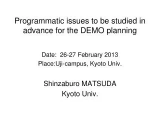
Programmatic issues to be studied in advance for the DEMO planning Date: 26-27 February 2013 Place:Uji-campus, Kyoto Univ. Shinzaburo MATSUDA Kyoto Univ.
Preface Fusion is an attractive long range big project. For such a long range and unprecedented physics and engineering convolution development, two approaches are necessary.
The polar method A firm view on the present basis
Reality We can go up, step by step. But the peak we may reach may not be the right one.
View from the air Two views should be combined
ITER Staged Approach toward Fusion Reactors Many countries define that “DEMO is the last integrated R&D machine” in the Fusion reactor development. Q=20~50 Q=10~20 Q~1 DEMO Reactor Experimental Reactor Large Tokamaks
If the DEMO is so defined, • Critical Issues to be challenged and overcome as an energy system 1)Plan for development of the control system for the fusion power plant; * How to maintain a constant fusion output. Development of a program by integrating plasma physics, diagnostics, actuators, simulation codes, and control system 2)Diverter concept and its physics and engineering feasibility: * How to handle heat and particles 3)Technical feasibility of the breeding blanket and long range plan: * Technical feasibility and scenario of the blanket handling high grade heat
4) Maintenance of the in-vessel components including hot cell design, recycling and back-end management scenario: * Design a large hot cell (factory) in line with development of scenarios for the replaced components, recycling and radioactive waste management. 5) Overall scenario for developing QA system: * Development of the design code and standard, safety regulation, operation and maintenance scenario, etc., taking into account of the feature of the fusion system.
Issue 1 Fusion Output Controlfrom the airplane view DEMO is the first demonstration machine of electricity production. Whether or not the fusion is really attractive and worthy for commercial use is an crucial question ? This evaluation will be made not by fusion researchers, but from the users (utility company, industry, public etc.). Accepting the advantage of the fusion characteristics, yet if the plant system is too much complicated, the users may not show interest in fusion plant. Now, what are required for fusion as an energy plant ?
About 80% of the total plant are for safety relevant systems
Requirements for the control of DEMO and beyond Steady Electric Power generation = steady fusion thermal output ⇒ Pf = constant 2. The control system should be as simple as possible. Actuators should be minimum. The frequency of the sudden stop must be lowest, once a year or less. Plasma detection and heating/fueling systems will be severely restricted in a high neutron environment and space. Recalling that fission control is just to keep recirculation water flow rate,
control command Actuator No 1 Actuator No 2 Plasma Central Control System Plasma Simulator Actuator No x Plasma diagnostics
The fusion thermal outputPfmust be expressed in terms of a function of the actuators Ai(i=1,2,3・・・) as Pf= f(A1, A2,A3・・・), precisely, Ai is a command signal. Q1Can we establish such a functional form of “ f ” by the time of completion of the DEMO reactor ? → Simulation codes system should includes both prediction and real time feedback control function. The codes should be able to express most of the plasma behavior, validated existing machines and by ITER before final application to DEMO. Such an integrated code system can be developed only by a long range, strategic manner, and require significant resources.
DEMO plant Conceptual Design Engineering Design Construction Operation ITER burning plasma Satellite Machines Development of Codes
Role of DEMO Demonstration of Electricity Generation Find a single scenario to start up and to maintain burning Find a minimum set of actuators and diagnostics Suggestion for future improvements Diagnostics for Control Q: what is a minimum set of diagnostics ? Concern : High neutron flux and fluence, induced gamma ray radiation, limited space and access competing with breeding blanket and shield.
Particular concern: + magnetic flux measurements for control + optical measurements Neutron flux: (Y.Someya) RIC: Radiation Induced Conductivity RIED: Radiation Induced Electrical Degradation RIEMF: Radiation Induced Electrical Motive Force Tolerance for neutron flux and fluence Influence of the structural materials and magnetic materials Sensitivity strongly depends on the location of the sensors. Find the sensor position and evaluate the feasibility.
In Japan, we launched a working body for “Sensing and Diagnostics coupled with Control of DEMO plant” A total of 30-40 members form the fields of , plasma control, diagnostics, remote handling, blanket, in vessel components, reactor structure, and reactor design get together to discuss in a coordinated way. Report will be completed a year later.
Issue 2 Divertor Can we mitigate the heat load to the solid material wall ? Even for ITER, it may be marginal. How to handle heat load in DEMO ?
A plane view on the power deposition : fusion output : power to the divertor plate the stationary power to be absorbed in the wall of the reactor: SlimCS total surface area of the first wall :880(670+210) if the radiation spreads into the plasma facing wall, the average power density: ~0.7 MW/ non-uniformity factor :assume the peak heat load to the 1st wall: 2.2MW/ in addition to the neutron wall load and divertor
If we confine the radiation due to detouched plasma in the divertor region, the average power loading will be assume non-uniformity factor the peak heat flux to the divertor region would be ~ 9MW/ in addition to the normal divertor heat load. Balancing of radiation into the first wall and the divertor region is inevitable, yet still it is marginal to handle these power levels.
Handling the Pulsed Heat Load • Thin plate approximation (1D) This model can be applied when the heat can be dissipated in the direction of the plate thickness in a time scale of interest, and the temperature gradient is negligible; : heat pulse width : plate thickness : 1D heat flow , c Then, the condition for melting of the plate is
Putting , , the condition for the excess heat is for melting for elastic-plastic change
Time scale and thickness Surface heating From the curve of most part of the heat can be hold within a depth of , ex. 0.4msec pulse, at 1273K W, Note: from eq.(1) and eq.(2) become equal only when
Polar method for divertor issues steady power handling how to mitigate ELM peak power A. Loarte et al: Plasma Phys. Cont. Fusion 45(2003) 1549, N.Oyama et al; NuclearFusion 45 (2005) 871
Peaking of ELM energy to the divertor • T.Eich et al: Inter ELM Power Decay Length for JET and ASDEX Upgrade and Comparison with Heuristic Drift-Based Model PRL107,215001(2011) • M.A.Makowski, et al., Analysis of a multi-machine database on divertor heat flux, Phys. of Plasmas, 19,056122(2012) Analysis of measurement for inter- ELM attached plasma. Scaling for power spread Power to the divertor surface is multiplied by the flux expansion factor, f ~ 3 (SlimCS), 6 (ITER)
Plane view If it is inevitable to decrease steady state heat load to the divertor target down to a level of ~ 10MW/, by developing a highly radiativedetouched plasma, how does the ELM heat superposition affect the divertor loading ? ex.in Eich 2011paper, time duration heat loading 99% (40ms) inter ELM, ~ 10MW/ 1 % (0.4ms) ELM, ~ 80MW/ base temperature of the divertor plate during inter- ELM may be about ELM power ~1.6 and :far from melting
Q : Does the heat accumulate due to repetition ? No,because the thermal diffusion depth for 40msec is 1.2mm The sharp peak temperature rise ( by one ELM propagates and decays into the deeper position and can be cooled with the bulk heat.
Whether or not the ELM gives damage to the surface of the divertor plate depends on the time contribution to one cycle, and its peak load. (A view from the plane)
It is also indicative that attention should be paid in deducing the peak heat flux from the measurement of the surface temperature. Namely, the heat flux can only be obtained by knowing a precise measurement of ELM pulse length (t) and the materials properties, through The other critical issues have to be visited taking into account of the priority and timing from the view point of power plant. Thank you for your attention !