Download
1 / 24
240 likes | 362 Views
Color spaces and JPEG. Colors. physically, color is electro-magnetic radiation (i.e. light with various wave length, between 390nm-750nm) percieved by the human eye a color is actually made from a combination o light radiations with different wave lengths electro-magnetic radiation spectrum:.

E N D
Colors • physically, color is electro-magnetic radiation (i.e. light with various wave length, between 390nm-750nm) percieved by the human eye • a color is actually made from a combination o light radiations with different wave lengths • electro-magnetic radiation spectrum:
Color spaces • color space = a mathematical model used to describe colors as tuples of numbers • RGB – Red, Green, Blue • CMYK – Cyan, Magenta, Yellow, Key Black • YUV(YCbCr) – Luminance, Chrominance blue, Chrominance red • HSV (HSB) – Hue, Saturation, Value • HSL – Hue, Saturation, Lightness
RGB • the color is specified as an additive combination of three primary colors: Red, Green, Blue • in addition, a white point must be specified for this color model • is mostly used in computer graphics • has a variation, RGBA, with alpha channel for transparency • black is 0 0 0 • white is 255 255 255
CMYK • the color is obtained by substracting from a white substrate the color components cyan, magenta, yellow and black • mainly used in paper printing
YUV • a color is composed from 3 components: Y-luminance (brightness of the pixel), U-blue chrominance, V-red chrominance • YPbPr is a scaled version of YUV used in analog television standards and YCbCr is a scaled version of YUV used in digital films and video and image compression standards like MPEG and JPEG
HSL and HSV • a color is described by 3 components: Hue (nuanta de culoare), Saturation(saturatia culorii) and lightness/brightness • HSV is also known as HSB (hue, saturation, brightness) • is mainly used by artists • HSL and HSV are cylindrical-coordinate representation of color points in the RGB (cartezian-coordinate) model
Color space conversions • RGB to YCbCr Y = 0.299*R + 0.587*G + 0.114*B Cb = 128 – 0.1687*R – 0.3312*G + 0.5*B Cr = 128 + 0.5*R – 0.4186*G – 0.0813*B • RGB (1-255) to CMY (0-1) C = 1 – (R / 255) M = 1 – (G / 255) Y = 1 – (B / 255)
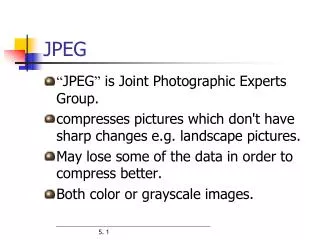
JPEG • is the name of an digital image compression standard created by ISO/IEC Joint Technical Committee 1, Subcommittee 29, Working Group 1 (ISO/IEC JTC 1/SC 29/WG 1); the standard is also recommended by ITU-T • stands from Joint Photographic Experts Group, the name of the committee that created the standard • is a lossy compression standard (different than lossless image compression like TIFF, GIF, PNG, BMP etc.) • JPEG has 2 operation modes: • baseline – lossy compression with a quality/compression factor from 1 to 100 • progressive – an image is compressed in multiple phases of progressively higher detail
JPEG baseline process • JPEG operates on 8x8 or 16x16 pixels macroblocks which are compressed independently • the JPEG encoder/decoder structure:
JPEG baseline compression algorithm 1. Color space conversion (to YUV) and possibly padding 2. Downsampling & block splitting 3. Discrete Cosine Transform (DCT) 4. Quantization 5. Entropy encoding 5.1 Zig-zag order of the coefficients, then Run-length encoding 5.2 Huffman encoding
1. Color space conversion (to YUV) and possibly padding • the colors of pixels are converted to YUV color space Y = 0.299*R + 0.587*G + 0.114*B U = 128 – 0.1687*R – 0.3312*G + 0.5*B V = 128 + 0.5*R – 0.4186*G – 0.0813*B • then the image is pixel padded at right and bottom so that width and height are multiple of 8 (16) bits
2. Downsampling & block splitting • YUV image is split in 8x8 or 16x16 blocks and downsampled: • 4:4:4 • 4:2:2 • 4:0:0
3. Discrete Cosine Transform (DCT) • the color values (YUV) are converted from the spatial (time) domain into frequency domain using the DCT formula bellow (similar to DFT – Discrete Fourier Transform): f(x,y) – pixel color (x=0..7, y=0..7) c(u)=c(v)=1/sqrt(2) for u,v=0 c(u)=c(v)=1 otherwise F(0,0) - DC coefficient F(u,v) – AC coefficients (u,v different than 0)
3. Discrete Cosine Transform (3) • Each 8x8 block of source image samples is effectively a 64-point discrete signal which is a function of the two spatial dimensions x and y. The DCT takes such a signal as its input and decomposes it into 64 orthogonal basis signals. Each contains one of the 64 unique two-dimensional (2D) “spatial frequencies’’ which comprise the input signal’s “spectrum.” The output of the DCT is the set of 64 basis-signal amplitudes or “DCT coefficients” whose values are uniquely determined by the particular 64-point input signal • the DCT tends to concentrate the strength (i.e. average intensity/color) of the block in the DC coefficient (the coef. of zero frequency in both dimensions; • the other coefficients contain variations of the average intensity/color and are called AC coefficients
4. Quantization • each DCT coefficient obtained at step 3 is divided by a quantization value
5. Entropy encoding • entropy enoding = zig-zag order + run-length encoding + Huffman encoding • Zig-zag order: The preceeding block is encoded as: 150, 80, 92, 26, 75, 20, 4, 18, 19, 3, 1, 2, 13, 3, 1, 0, 1, 2, 2, 0, 0, 0, 0, 0, 1, 1, 0, 0, 0, 0, 0, 0, 0, 0, 0, 0, 0, 0, 0, 0, 0, 0, 0, 0, 0, 0, 0, 0, 0, 0, 0, 0, 0, 0, 0, 0, 0, 0, 0, 0, 0, 0, 0, 0
Entropy encoding of the DC coef. • the DC coefficient of a block is encoded separately than the AC coefficients of that block • the difference between the current DC and the DC from the previous block is encoded as 2 symbols: (SIZE) (AMPLITUDE) • SIZE = is the number of bits used to encode AMPLITUDE; is encoded as a variable-length code(VLC) from a Huffman table • AMPLITUDE = is the amplitude on the coefficient difference; is encoded as a variable-length integer (VLI) code whose length in bits is given in the table from the next slide
Entropy encoding of the AC coefs. • AC coefficients are parsed in a zig-zag order and then run-length encoded and then Huffman encoded • in general, the sequence of characters: a b c c c c d d d e f g g g g g g h h is run-length encoded into the sequence: a b 4c 3d e f 6g 2h • in JPEG, each non-zero AC coef. is encoded in combination with the runlength (consecutive number) of zero-valued AC coefs. into a pair of symbols: (RUNLENGTH, SIZE) (AMPLITUDE) where SIZE and AMPLITUDE are like the ones used for the DC coef. and RUNLENGTH – the number of consecutive zero-valued AC coefs. in zig-zag order preceeding the nonzero AC coef. being represented • symbol 1 is encoded as a variable-length code(VLC) from a Huffman table • symbol 2 is encoded as a variable-length integer (VLI) code whose length in bits is given in the previous table
Entropy encoding of the previous quantization block example • the zig-zag order of coefficients: 150, 80, 92, 26, 75, 20, 4, 18, 19, 3, 1, 2, 13, 3, 1, 0, 1, 2, 2, 0, 0, 0, 0, 0, 1, 1, 0, 0, 0, 0, 0, 0, 0, 0, 0, 0, 0, 0, 0, 0, 0, 0, 0, 0, 0, 0, 0, 0, 0, 0, 0, 0, 0, 0, 0, 0, 0, 0, 0, 0, 0, 0, 0, 0 is run-length encoded (assume DC in the previous block is 0) into: (8)(150), (0,7)(80), (0,7)(92), (0,5)(26), (0,7)(75), (0,5)(20), (0,3)(4), (0,5)(18), (0,5)(19), (0,2)(3), (0,1)(1), (0,2)(2), (0,4)(13), (0,2)(3), (0,1)(1), (1,1)(1), (0,2)(2), (0,2)(2), (5,1)(1), (0,1)(1), (0,0) (0,0) – is EOB (End Of Block) • the above sequence is Huffman (VLC and VLI) encoded into: (111110)(10010110), (11111000)(1010000), (11111000)(1011100), (11010)(11010), (11111000)(1001011), (11010)(10100), (100)(100), (11010)(10010), (11010)(10011), (01)(11), (00)(1), (01)(10), (1011)(1101), (01)(11), (00)(1), (1100)(1), (01)(10), (01)(10), (1111010)(1), (00)(1), (1010)
JFIF File Format (.jpg) – see class dmms.jpeg.JPGInfo.java The format of a JPEG/JFIF file is: • Header: • It occupies two bytes. • 0xff, 0xd8 (SOI : Start Of Image ) (these two identify a JPEG/JFIF file). • Segments or markers: • Following the SOI marker, there can be any number of segments or markers such as: • APP0..APP15, SOF0..SOF15, DQT, DHT, SOS, JPG, JPG0..JPG13, DAC, DNL, DRI, DHP, EXP, RST0..RST7, TEM, COM. • An APP0 segment immediately follows the SOI marker. • Trailer: • It occupies two bytes. • 0xff, 0xd9 (EOI: End of Image) (these two identify end of image). Note: any number of 0xff bytes between two segments (markers) must be ignored.