Download
1 / 29
330 likes | 614 Views
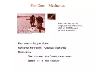
Cm_part22. Continuum Mechanics, part 22. Kinematics_2 Small deformation theory Right and left Cauchy-Green deformation tensors Stretch, polar decomposition Rate of polar rotation. The plane stress induced by Cauchy strain is. % rigrot.m

E N D
Cm_part22 Continuum Mechanics, part 22 Kinematics_2 Small deformation theory Right and left Cauchy-Green deformation tensors Stretch, polar decomposition Rate of polar rotation
% rigrot.m % strain and stress "induced" due to a rigid body rotation clear ommax=6; omrange=1:ommax; ss=zeros(3,ommax);ee=zeros(3,ommax); splot=zeros(ommax,1);eplot=zeros(ommax,1); mu=0.3; E=2.1e11; const=E/(1-mu^2); d=const*[1 mu 0; mu 1 0; 0 0 (1-mu)/2]; for om=omrange om; omr=om*pi/180;e1=cos(omr)-1; eplot(om)=e1; ep=[e1 e1 0]; ee(:,om)=ep';sigma=d*ep'; splot(om)=sigma(1,1); ss(:,om)=sigma; end figure(1) subplot(2,1,1);plot(0:ommax,[0 eplot']); title('strain11 vs. rigid body rotation [degrees]'); subplot(2,1,2);plot(0:ommax,[0 splot']); title('stress11 [N/m^2] vs. rigid body rotation [degrees]') % end of rigrot % rigrot.m % strain and stress "induced" due to a rigid body rotation clear ommax=6; omrange=1:ommax; ss=zeros(3,ommax); ee=zeros(3,ommax); splot=zeros(ommax,1); eplot=zeros(ommax,1); mu=0.3; E=2.1e11; const=E/(1-mu^2); d=const*[1 mu 0; mu 1 0; 0 0 (1-mu)/2]; for om=omrange om; omr=om*pi/180; e1=cos(omr)-1; eplot(om)=e1; ep=[e1 e1 0]; ee(:,om)=ep'; sigma=d*ep'; splot(om)=sigma(1,1); ss(:,om)=sigma; end % ee; % ss; figure(1) subplot(2,1,1);plot(0:ommax,[0 eplot']); title('strain11 vs. rigid body rotation [degrees]'); subplot(2,1,2);plot(0:ommax,[0 splot']); title('stress11 [N/m^2] vs. rigid body rotation [degrees]') % end of rigrot
{dx}=[F]{da} In one step Right polar decomposition F = RU
Time derivative of a vector is the velocity of its end point