Download

1 / 18
180 likes | 264 Views
This tool suite offers power consumption analysis for FPGAs post-synthesis, overcoming limitations of existing tools like spreadsheets, enabling intuitive power visualization, analysis, and optimization. It leverages JHDL data structure and EDIF parser for early power estimation and detailed profiling. The architecture benefits designers by facilitating high-level design exploration and identifying power inefficiencies. It integrates power modeling, component capacitance analysis, and wire power modeling for efficient power optimization.

E N D
Integrated Tool Suite for Post Synthesis FPGA Power Consumption Analysis Matthew French, Li Wang University of Southern California, Information Sciences Institute Tyler Anderson, Michael Wirthlin Brigham Young University
Internal Power Consumption Number of F-F’s Power (mW) Clocking Frequency (MHz) Voltage (V) FPGA Power Trends & Needs • Number of logic blocks & maximum operating frequency track Moore’s Law • Voltage reduction is slower • Resulting power increase is exponential • Power needs to be a first class design constraint • Limited power tools available • Spreadsheets • Manual entry • Prone to guess-timation • XPower (post-routing) • At end of design cycle • Profiled after timing simulation • Time intensive • Unwieldy file sizes • Limited Reporting • Only total power consumed • No ability to capture power transients • Limited design path if specifications not met • Routing tools optimize only throughput Power calculated assuming 80% device utilization, 80% peak clock frequency, 12.5% toggling rate. Internal logic only, no I/O.
Power Tools: Goals • Push power analysis, visualization, and optimization to front of the tools chain: • Analyze power consumption at logic simulation with two levels of accuracy • Pre-place-and-route, using heuristic estimates based on fanout • Back-annotated with precise post-place-and-route RC data • Visualize by providing intuitive views to help the designer rapidly find and correct inefficient circuits, operating modes, data patterns, etc. • Optimize systems by automatically identifying problem paths and suggesting improvements • Benefits • Closer to logical level and design entry • Power profiling during functional simulation • Early estimation before place and route • Automatic specific resource utilization power details • Facilitates high level design alternative exploration FPGA Tool Flow Proposed Power Tool Entry Point Current Power Tool Entry Point
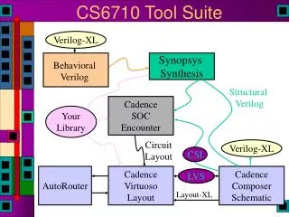
3rd Party Tools JHDL Data Structure EDIF Netlist EDIF Data Structure EDIF Parser Manipulation Tools Tool Backbone: JHDL & EDIF Parser • Leverage JHDL simulation Environment with EDIF Parser circuit manipulation • JHDL • Java-based structural design tool for FPGAs • Circuits described by creating Java Classes • Design libraries provided for several FPGA families • http://www.jhdl.org • JHDL design aides • Logic simulator & waveform viewer • Circuit schematic & hierarchy browser • Module Generators • Circuit designer does not need to know Java! • EDIF Parser • Supports multiple EDIF files • Virtex2 libraries and memory initialization • Support for “black boxes” • No JHDL wrapper required • http://splish.ee.byu.edu/reliability/edif/ • Verified: Synplicity, Synplcity Pro, Coregen, System Generator, Chipscope JHDL Environment EDIF Parser
To Target .ncd .ncd Place & Route Xpower Map Source Code VHDL Verilog JHDL Xilinx Tool Flow Bitgen .pwr Synthesis EDIF Routed Circuit Model EDIF Parser JHDL Power Tools Power Analysis & Visualization Power Tool Flow: Timing-Level • Event Model Restructured • Tool Interoperability • Cross-probing Enabled • Support dynamic insertion of 3rd party (Power) tools • Circuit APIs in place • Graphical User Interfaces (GUI) support
Power Visualization Tool • Two views: • Instantaneous vs. cumulative power consumption over time • Sorted tree view of “worst offenders” • Integrated “cross-probing” with existing JHDL tools • Unified Environment • Allows Experimentation • Smart Re-use of CPU Memory • Help rapidly identify inefficient circuits and operating modes • Per-cell / per-bit granularity • Simulation trigger on power specification Cross Probing
Post Synthesis Level Power Modeling • Power Modeling • Quiescent power based on total circuit size • Dynamic Power • Toggle Rates (Data Dependant) • Components Used • Routing Interconnect • Actual quiescent and dynamic power not known until circuit is placed and routed • Leverage existing JHDL tool environment • Toggling rates derived from simulator • Will lose glitching information • Components known from EDIF or JHDL primitives • Component capacitance imported from Xpower • How to model routing interconnect? • Do not have exact routing information at synthesis • Routing tools can pick different route each iteration • Interconnect length and combinations vary Xpower Component Capacitance Xpower Interconnect Capacitance
Wire Power Model Analysis • Developed power tools to analyze relationships • Can plot capacitance vs • Fanout • Programmable Interconnect Points • Wire Length • Total Number of Nets • Total Number of Components • Which relationships maintain correlation from synthesis to place and route? • Optimizer removes components, nets • Can also use tools to judge routing quality • Identify Outliers • Information Available to do Power Weighted Placement and Routing • Use Placement Macros in JHDL • Use UCF placement and/or timing constraints Optimization Candidates
Low Fanout Capacitance Variance Logic Switch • Not all routes are created Equal • Up to 60% variance on “same” route length • East-West vs North-South Bias • Switches sometimes use Doubles instead of Direct Connects 2.37 pF (#4791) YQ -> G4 (omux-B4) 2.45 pF (#2727) YQ -> F2 (omux-B3) 1.46 pF (#2768) YQ -> F4 (omux-A2) Direct vs Double 0.75 pF (#131) YQ -> F2 (omux-A7) Direct Connect Double Wire
Placement Macros Capacitance vs Fanout • Fanout model well correlated • Secondary fit line corresponds to Macros • High variance at low fanout • Achieving 4.3% average error, 16% variance • Explored device utilization models as well
Place & Route Map Xpower Bitgen Synthesis EDIF JHDL Resulting Power Tool Flow To Target .ncd .ncd Source Code VHDL Verilog JHDL Xilinx Tool Flow .pwr Virtex II Power Model Routed Circuit Model EDIF Parser Power Tools Power Analysis & Visualization
Place & Route Xpower bitgen .ncd Xilinx Tool Flow Ngdbuild & Map .ncd .ucf vcd Tool Verification Optimization Verification vhd ModelSim Power Optimization Approach • Influence Xilinx Place&Route tools for power efficiency • Minimize clock/wire lengths of high power nets • Use power analysis tools to identify hot-spots and generate constraints • Timing constraints on non-clock signals • Location constraints on sink flip-flops of clock signals • Verify power optimization approaches • Use final circuit timing model to verify power savings Timing Constraint (ns) Placement Constraint (X,Y) EDIF EDIF Parser Power Tools
Timing Constraint Power Optimization • Wire power is optimized by reducing length • MAXDELAY constraint in UCF file defines the maximum latency a wire has • Power tools contain Wire Table database • Sortable by: Average power, Toggling rate, Fanout, Load • Apply constraints Default Constraints Constraint Freq : 50 MHz Operating Freq : 50 MHz Poor Power Efficiency Wire Table Power Timing ConstraintsConstraint Freq : 100 MHz Operating Freq : 50 MHz Better Power Efficiency
Timing Constraint Power Optimization: Preliminary Results • Power is reduced by from –1.4% to 11.8% • More constraints are not necessarily better • Can also vary amount of timing that nets are constrained by • Circuits still meet original timing specification requirements
Location Constraint Power Optimization More Power Efficient Less Power Efficient • Power Optimization Guidelines • Minimize clock zone utilization • Group flip-flops as tightly as possible • Group flip-flops closer to clock trunks Reduce clock paths by putting constraints on flip-flops locations, thus reducing the clock capacitance and power.
Clock Table Location Constraint Power Optimization Interface • Clock table can be sorted by power, number of flip-flops etc. • Users can select locations of flip-flops - Users can select how tightly flip-flops are placed - Users can define the area where flip-flops are placed The tool checks the validity of constraint areas. - Users can select which flip-flop groups are added with the constraints
Location Constraint Power Optimization Preliminary Results Unconstrained • Individual clock net improvement ranged from -4% to 57% • Achieve up to 22.9% total power improvement • Circuits still meet timing requirement if IO buffer flip-flops are left in IOBs • Power could be further reduced if IO buffer flip-flops are not constrained to be within IOBs Constrained
Conclusions • Post-synthesis level power modeling is feasible • Some accuracy trade-offs inevitable • Quicker power results enable • Capability to determine power specifications early in the design flow • Feedback on design-level circuit power ramifications • Tighter feedback loop to designer for more design iterations • Optimization • Preliminary results encouraging • Tools do not alter original circuit functionality & use COTS inputs • Developing optimization algorithms & routines • Tools are open source: http://rhino.east.isi.edu • This research made possible by a grant from the NASA Earth-Sun System Technology Office