Download
1 / 63
630 likes | 730 Views
P561: Network Systems Week 4: Internetworking II. Tom Anderson Ratul Mahajan TA: Colin Dixon. Today. Internet routing (BGP) Tunneling and MPLS Wireless routing Wireless handoffs. Internet today. Key goals for Internet routing. Scalability Support arbitrary policies

E N D
P561: Network SystemsWeek 4: Internetworking II Tom Anderson Ratul Mahajan TA: Colin Dixon
Today • Internet routing (BGP) • Tunneling and MPLS • Wireless routing • Wireless handoffs
Key goals for Internet routing • Scalability • Support arbitrary policies • Finding “optimal” paths was less important • (Supporting arbitrary topologies)
Internet routing overview • Two-level hierarchy for scalability • Intra-domain: within an ISP (OSPF, MPLS) • Inter-domain: across ISPs (BGP) • Path vector protocol between Ases • Can support many policies • Fewer messages in response to small changes • Only impacted routers are informed
Path vector routing • Similar to distance vector routing info includes entire paths 192.4.23, [3, 7] 192.4.23, [7]
Policy knobs • 1. Selecting one of the multiple offered paths • 2. Deciding who to offer paths 192.168.1.3/24, [2, 4] AS 2 AS 1 AS 4 AS 3 192.168.1.3/24, [3, 4] 192.168.1.3/24, [4, 1] AS 2 AS 4 AS 1 AS 3 192.168.1.3/24, [4, 1]
Path vector vs. link state vis-à-vis policy • With path vector, implementing the policy above requires only local knowledge at AS3 • With link state, AS3 would need to know the policies of other ASes as well 1 0 D 3 AS3 preferences [31o] [320] [3210][3120] 2
Typical routing policies • Driven by business considerations • Two common types of relationships between ASes • Customer-provider: customer pays provider • Peering: no monetary exchange • When selecting routes: customer > peer > provider • When exporting routes: do not export provider or peer routes to other providers and peers • Prefer routes with shorter AS paths Peer or provider Peer or provider X Customer Customer
BGP limitations • Path quality • Scale • Convergence • Security
Path quality with BGP • Combination of local policies may not be globally good • Longer paths, asymmetric paths • Shorter “detours” are often available • Example: hot potato routing A B
Scaling pressures on BGP • Too many prefixes (currently ~280K) • Major factors behind growth: multi-homing and traffic engineering 192.168.0.0/16 192.168.0.0/17 192.168.0.0/16 Provider1 Provider Customer Customer Provider 2 192.168.0.0/16 192.168.128.0/17
BGP convergence (1/4) • Temporary loops during path exploration • Differentiating between failure and policy-based retraction can help but not completely 1 D 0 3 2
BGP convergence (2/4) • Persistent loops can also form in BGP • Fundamentally, the combination of local policies may not have a unique global solution 0 1 To get to D, X prefers [X, (X+1) mod 3] [X] Others D 2
BGP convergence (3/4) • Several other issues have been uncovered • Interaction with intra-domain routing • Interaction with traffic engineering extensions • Interaction with scalability extensions
BGP convergence (4/4) • Q: What saves us in practice? • A: Policy! (No guarantees, however) 1 0 1 D 0 3 D Policy reduces the number of valid paths Policy makes some preferences rare 2 2
BGP security • Extreme vulnerability to attacks and misconfigurations • An AS can announce reachability to any prefix • An AS can announce connectivity to other Ases • Many known incidents • AS7007 brought down the whole internet in 1997 • 75% of new route adverts are due to misconfigs[SIGCOMM 2002] • Commonly used for spamming • Technical solutions exist but none even close to deployment • Incentives and deployability (Week 10)
Tunneling • Encapsulating one protocol within another • The blue sources, destinations, networks are oblivious to tunneling • The yellow network does not care if it carries blue (or green) packets TunSrc TunDst Src Dst
Tunneling is broadly useful technique • Used widely today • Secure access to remote networks (VPNs) • Your laptop to corporate networks • Between different sites of a company • MPLS • 6to4 • GRE • SSH tunnels • …. • Think of it as a generalization of traditional layering
MPLS LER LSR LSR LER LSR LER LSR LSR LER
Benefits of MPLS (1/3) • LSRs do not understand or maintain state for IP • Can yield higher performance • Without n2 pair-wise tunnels LER LSR LSR LER LSR LER LSR LSR LER
Benefits of MPLS (2/3) • Traffic engineering (load balancing) LER LSR LSR LER LSR LER LSR LSR LER
Benefits of MPLS (3/3) • Separation of traffic for security or for QoS LER LSR LSR LER LSR LER LSR LSR LER
Downsides of MPLS • Unnecessary overhead • If all you want is IP forwarding • If link state routing can provide effective traffic engineering • Robustness to failures • Setting up a complete virtual circuit takes time • Fast reroute works only for a handful for failures • Opacity • Traditional diagnosis tools do not work • Complexity • Requires more configuration at routers
MPLS adoption • Pretty widespread • Almost all tier-1 ISPs have deployed MPLS • It offers tools that network adminsbadly need • Practical concerns trumped purist views
Why is wireless routing different? • Mobility and fast changing conditions • Packet losses • Interference
First generation of protocols • Focus on mobility and changing conditions • Used hop count as the quality metric • Reactive route computation was more popular • To avoid unnecessary topology maintenance overhead • Examples: DSR, AODV
Hop count limitations • It minimizes the number of hops and thus prefers longer links • But longer links tend to have more loss • Need more retransmissions for successful reception • Retransmissions can consume more spectrum resources than using shorter hops • Need to balance hops and losses
All links are not the same MIT’s indoor testbed
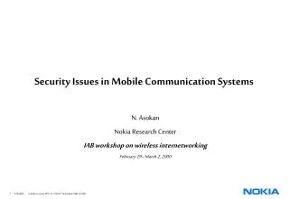
Link qualities in Roofnet Broadcast packet delivery probability 70-100% 30-70% 1-30% 1 kilometer
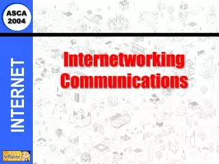
Delivery probabilities in Roofnet Broadcast Packet Delivery Probability > two-thirds of links deliver less than 90% Node Pair
ETX: Expected transmissions • Estimate number of times a packet has to be retransmitted on each hop • Use probes to calculate forward and reverse loss rate to each neighbor • Select the path with least total ETX • Takes longer paths only when they are better
ETX avoids low-throughput paths Results on MSR testbed(courtesy Jitu Padhye)
ETX shortcomings • Assumes that all transmissions are equal • In reality, different transmissions use different amount of spectrum • Assumes a simplistic interference model • Cross-flow interference not directly accounted • Worst-cast self-interference • Ignores the broadcast nature of wireless
ETT: Expected transmission time • Generalizes ETX to the case of multiple bit rates • Directly measures spectrum resources used • On a link with loss rate p, bitrateB, packet size S 12 Mbps 10% loss 48 Mbps 20% loss [Routing in Multi-radio, Multi-hop Wireless Mesh Network, MOBICOM 2004]
Is one path better than the other? Bad Good Source Relay Sink Good Bad Source Relay Sink Hint: ETT (or ETX) of both is same
Unpredictable wireless performance Bad Good Source Relay Sink Good Bad Source Relay Sink bad-good bad-good UDP throughput (Kbps) UDP throughput (Kbps) good-bad 2x good-bad Loss rate on the bad link Source rate (Kbps)
Predictable performance optimization Measure the RF profile of the network Constraints on sending rate and loss rate of each link Find compliant source rates that meet the objective [Predictable performance optimization for wireless networks, SIGCOMM 2008]
Measurements One or two nodes broadcast at a time Yields information on loss and deferral probabilities Measure the RF profile of the network Constraints on sending rate and loss rate of each link Find compliant source rates that meet the objective
Modeling Measure the RF profile of the network • O(n2) constraints • Link throughput is a function of loss rate and tx probability • Link tx probabilityis a function of tx probability of other links and deferral probability • Link loss rate depends on tx probability of other links • Tx probability is bounded by a function of loss rate Constraints on sending rate and loss rate of each link Find compliant source rates that meet the objective
Optimization Inputs: • Traffic matrix • Routing matrix • Optimization objective Output: • Per-flow source rate Measure the RF profile of the network Constraints on sending rate and loss rate of each link Find compliant source rates that meet the objective
Leveraging wireless broadcast 2 3 A B 1 Traditional routing dst src C A B An opportunity dst src C
ExOR: Extremely opportunistic routing • Source identifies and prioritized list of relays • Source groups packets into a batch and transmits • Nodes run an agreement protocol • The highest priority relay announces what it received • The next relay transmits packets not received by higher priority relays • Finally, the source retransmits what nobody got [Opportunistic Routing in Multi-Hop Wireless Networks, SIGCOMM 2005]
ExOR: Initial transmission 9 8 7 6 5 4 3 2 1 0 9 8 7 6 5 4 3 2 1 0 A B 9 8 7 6 5 4 3 2 1 0 dst src C 9 8 7 6 5 4 3 2 0 9 8 7 6 5 4 3 2 1 0 Source transmits the entire batch
ExOR: Agreement protocol Step4:Transmit 6Ack 0,1,2,3,5,6,7,9 Step2:Transmit 1,2,5,7Ack0,1,2,3,5,7 9 8 7 6 5 4 3 2 1 0 9 8 7 6 5 4 3 2 1 0 A B 9 8 7 6 5 4 3 2 1 0 dst src C 9 8 7 6 5 4 3 2 0 Step5:Transmit 4,8 9 8 7 6 5 4 3 2 1 0 Step1:Ack0, 3 Step3:Transmit 9Ack 0,1,2,3,5,7,9
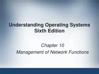
ExORperformance improvement 1.0 0.8 0.6 Cumulative Fraction of Node Pairs 0.4 0.2 ExOR Traditional 0 0 200 400 600 800 Throughput (Kbits/sec)