Download
1 / 35
400 likes | 480 Views
Learn about the structure, functions, and design principles of steam generator furnaces in power plants for efficient energy generation. Detailed information on combustion, heat transfer, and furnace geometry.

E N D
Anatomy & Organs of Power Plant Steam Generators By P M V Subbarao Professor Mechanical Engineering Department I I T Delhi Structure of A Two in One Device– Combustor and Heat Exchanger……
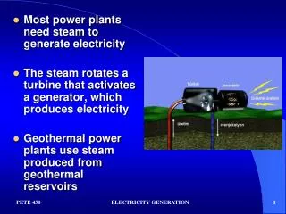
Details of Basic Processes • Generation of Thermal Energy – Using Natural Resources. • Chemical Energy: Microscopic Potential Energy • Conversion of MPE to MKE • Combustion Sciences. • Transfer of Thermal Energy to working fluid. • Transfer MKE of gas to MKE of steam. • Science of Heat Transfer.
African Elephant Indian Elephant A True Design Reason behind Geometry of Natural Systems….. Mammoths
Hot Flue Gas Thermal Structure SH Steam Rise in Enthalpy of Steam Convection HT Drop in Enthalpy of Flue Gas Convection & Radiation HT Mechanism of Heat Transfer Thermal Structure Sink /Demand Source/Supply Phenomenological Model
DPNL SH R H T R drum screen tubes Platen SHTR stack LTSH Economiser BCW pump Furnace APH ESP ID Fan Bottom ash Components of A Steam Generator System : Heat Transfer
Steam Generator Furnace : Function -1 • Structurally boiler furnace consists of the combustion space surrounded by water walls. • The furnace is designed to perform two functions simultaneously, namely: • Release of the chemical energy of fuel by combustion • The first task of combustion technology is • to burn the fuel efficiently and steadily, • to inhale controlled excess air (as little as possible), • To generate a flame with controlled shape which will generate lowest amount of pollutants.
Steam Generator Furnace : Function - 2 • Transfer of heat from the furnace to the working fluid inside the water walls. • The important task of furnace heat removal is to produce a controlled Furnace Exit Gas Temperature (FEGT). • FEGT is an important aspect of boiler safety & Efficient Operation.
Furnace Exit Hot Exhaust gases Heat Radiation & Convection Flame Burner
General Design Principles • The furnace should provide the required physical environment and the time to complete the combustion of fuel. • The furnace should have adequate radiative heating surfaces to cool the flue gas sufficiently to ensure safe operation of the downstream convective heating surface. • Aerodynamics in the furnace should prevent impingement of flames on the water wall and ensure uniform distribution of heat flux on the water wall. • The furnace should provide conditions favoring reliable natural circulation of water through water wall tubes. • The configuration of the furnace should be compact enough to minimize the amount of steel and other construction material.
Determination of Furnace Size • What is the boundary of a furnace? • The boundary of a furnace is defined by • Central plane of water wall and roof tubes • Central lines of the first row super heater tubes. • = 30 to 50O • > 30O • = 50 to 55O • E = 0.8 to 1.6 m • d = 0.25 b to 0.33 b
Furnace Depth & Height • Depth (a) to breadth (b)ratio is an important parameter from both combustion and heat absorption standpoint. • Following factors influence the minimum value of breadth. • Capacity of the boiler • Type of fuel • Arrangement of burners • Heat release rate per unit furnace area • Capacity of each burner • The furnace should be sufficiently high so that the flame does not hit the super heater tubes. • The minimum height depends on type of coal and capacity of burner. • Lower the value of height the worse the natural circulation.
Heat Available to The Furnace Walls • Incomplete combustion loss • Unburned Carbon loss • Loss due to slag • Energy brought in by preheated air & fuel. • An exact fraction of this total heat should be absorbed in furnace. • The designer provides an environment for the same.
Tangential fired furnace* Down fired furnace Burner Arrangement & Flame Shapes • An array of burner installed on walls or at corners of furnace • Fuel and combustion air projected from the each burner create a complex shape of flame. • Intense mixing of fuel and air stream at the centre Opposed wall fired furnace
Radiative HT from Flame to Water Wall • Emitted Radiation heat flux of flame: • Emitted Radiation = Available Heat • Heat flux absorbed by walls : Thermal efficiency factor, y. • The rate of heat absorption
Furnace Exit Gas Temperature • The temperature of products of combustion at the exit of the furnace is called FEGT. • Defines the ratio of furnace heat absorption to outside heat absorption. • High FEGT – Compact furnace & Large secondary section • FEGT < Ash Deformation Temperature. • Generally FEGT = Ash Softening Temperature – 100. FEGT is a Right Measure of Steam Generator Health ! A Healthy SG will Always Perform Better !!! A SG Always Healthy will Perform Better !
Limits on Furnace Exit Gas Temperature • FEGT is an important design parameter. • Defines the ratio of furnace heat absorption to Convection heat absorption. • FEGT < Ash Deformation Temperature. • FEGT = AST – 100 • FEGT < 1100 0C – Strong slag • FEGT < 1200 0C – Moderate slag • FEGT < 1250 0C -- Weak slag • Any design procedure can be used but it should satisfy the requirements of FEGT.
Daily Variation of FEGT 1225 1200 1175 1150 1125 1100 0C
Instantaneous Dirtiness of Water walls • During the operation of steam generator, ash and slag deposits on the boiler water walls and other heat transfer sections. • Thermal conductivity of the deposits are much less than steel. • Furnace dirtiness decreases radiation heat transfer to water walls. • FD Enhances the Furnace Exit Gas Temperature. • Less steam is generated in the furnace. • More heat is transferred to superheaters. • Leads to increase in turbine inlet temperature. • Special water spray is automatically activated to attemparate the Turbine inlet steam. • This leads to increased chimney gas temperatures.
Impact of Dirtiness on SG Performance • Dirtiness of furnace leads to increased chimney gas temperatures. • Enhances the metal temperatures of superheaters. • Increases the probability of tune leakage/failure. • Furnace and convective pass slagging and fouling have a detrimental effect on boiler performance and emissions. • High FD is responsible for the primary cause of reduced operating efficiency in coal-fired boilers.
The Act of Sootblowing • Sootblowing is used to control the level of ash and slag deposits on the boiler heat transfer sections. • On-line cleaning of localized areas is performed by sootblowers using high pressure steam or air. • Wall blowers are used to remove slag from furnace water walls. • Retractable blowers are used to clean the convective pass of the boiler. • Furnace cleaning increases radiation heat transfer to water walls and reduces the Furnace Exit Gas Temperautre.
Regular sootblowing results in : higher furnace exit gas temperature (FEGT), higher steam temperature, higher desuperheating spray flows, and higher Nox emissions. As the convective pass of a boiler slags and fouls, heat transfer decreases, resulting in a decrease in steam temperature, decrease in desuperheating spray flows, and an increase in flue gas temperature at the boiler exit. For best boiler performance it is important to maintain an optimal balance between furnace and convection pass heat transfer. Positive Impact of Sootblowing
TYPES OF SOOT BLOWERS TYPE OF BLOWERS APPLICATIONS - LONG RETRACTABLE CONVECTION ZONE SOOT BLOWER (SH, RH, LTSH, ECO) • WALL DESLAGGER FURNACE WALL • ROTARY SOOT BLOWERSAIR HEATERS Typical 500MW plant Soot Blowing system: Wall Blowers - 88 Nos + (16 No. FP.) Long Retractable Blowers - 36 Nos + (28 No.FP ) Air Heater Blowers - 4 Nos.
Arrangement of Soot Blowers in A 500 MW Steam Generator
Effects of Sootblowing on Unit Operation and Emissions • While ash and slag deposition is a gradual process, sootblowing results in an abrupt change in local heat transfer. • This can result in unfavorable energy distributions among different heat transfer sections, loss of thermal performance and increased unit heat rate. • Figure shows the effect of sootblowing on furnace cleanliness (expressed as FEGT). • Next Figure shows the effect of cleaning of a platen superheater on its surface cleanliness.