Download
1 / 57
570 likes | 702 Views
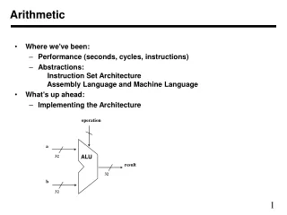
Numbers and Arithmetic. Hakim Weatherspoon CS 3410, Spring 2013 Computer Science Cornell University. See: P&H Chapter 2.4 - 2.6, 3.2, C.5 – C.6. Big Picture: Building a Processor. memory. register file. inst. alu. +4. +4. addr. =?. PC. d in. d out. control. cmp. offset.

E N D
Numbers and Arithmetic Hakim Weatherspoon CS 3410, Spring 2013 Computer Science Cornell University See: P&H Chapter 2.4 - 2.6, 3.2, C.5 – C.6
Big Picture: Building a Processor memory registerfile inst alu +4 +4 addr =? PC din dout control cmp offset memory new pc target imm extend A Single cycle processor
Goals for Today • Binary Operations • Number representations • One-bit and four-bit adders • Negative numbers and two’s compliment • Addition (two’s compliment) • Subtraction (two’s compliment) • Performance Example • Build a circuit (e.g. voting machine) • Building blocks (encoders, decoders, multiplexors)
Number Representations • Recall: Binary • Two symbols (base 2): true and false; 0 and 1 • Basis of Logic Circuits and all digital computers • So, how do we represent numbers inBinary (base 2)?
Number Representations • Recall: Binary • Two symbols (base 2): true and false; 1 and 0 • Basis of Logic Circuits and all digital computers • So, how do we represent numbers inBinary(base 2)? • We know represent numbers in Decimal (base 10). • E.g. 6 3 7 • Can just as easily use other bases • Base 2 — Binary • Base 8 — Octal • Base 16 — Hexadecimal 102 101100 1 0 0 1 1 1 1 1 0 1 2928 27 2625 24 23 22 21 20 0o 1 1 7 5 0x 2 7 d 83 82 8180 162161160
Number Representations • Recall: Binary • Two symbols (base 2): true and false; 1and 0 • Basis of Logic Circuits and all digital computers • So, how do we represent numbers inBinary(base 2)? • We know represent numbers in Decimal (base 10). • E.g. 6 3 7 • Can just as easily use other bases • Base 2 — Binary • Base 8 — Octal • Base 16 — Hexadecimal 6∙102 + 3∙101 + 7∙100 = 637 102 101100 1∙29+1∙26+1∙25+1∙24+1∙23+1∙22+1∙20 = 637 1∙83 + 1∙82 + 7∙81+ 5∙80= 637 2∙162 + 7∙161 + d∙160 = 637 2∙162 + 7∙161 + 13∙160 = 637
Number Representations: Activity #1 Counting • How do we count in different bases? • Dec (base 10)Bin (base 2) Oct (base 8)Hex (base 16) 0 1 2 3 4 5 6 7 8 9 10 11 12 13 14 15 16 17 18 . . 99 100 0 1 10 11 100 101 110 111 1000 1001 1010 1011 1100 1101 1110 1111 1 0000 1 0001 1 0010 . . 0 1 2 3 4 5 6 7 10 11 12 13 14 15 16 17 20 21 22 . . 0 1 2 3 4 5 6 7 8 9 a b c d e f 10 11 12 . . 0 1 2 3 4 5 6 7 8 9 a b c d e f
Number Representations • How to convert a number between different bases? • Base conversionvia repetitive division • Divide by base, write remainder, move left with quotient • 637 10 = 63 remainder 7 • 63 10 = 6 remainder 3 • 6 10 = 0 remainder 6 lsb (least significant bit) msb (most significant bit)
Number Representations • Convert a base 10 number to a base 2 number • Base conversion via repetitive division • Divide by base, write remainder, move left with quotient • 637 2 = 318 remainder 1 • 318 2 = 159 remainder 0 • 159 2 = 79 remainder 1 • 79 2 = 39 remainder 1 • 39 2 = 19 remainder 1 • 19 2 = 9 remainder 1 • 9 2 = 4 remainder 1 • 4 2 = 2 remainder 0 • 2 2 = 1 remainder 0 • 1 2 = 0 remainder 1 • 637 = 10 0111 1101 (can also be written as 0b10 0111 1101) lsb (least significant bit) msb (most significant bit) msb lsb
Number Representations • Convert a base 10 number to a base 16 number • Base conversion via repetitive division • Divide by base, write remainder, move left with quotient • 637 16 = 39 remainder 13 • 39 16 = 2 remainder 7 • 2 16 = 0 remainder 2 • 637 = 0x 2 7 13 = 0x 2 7 d • Thus, 637 = 0x27d lsb dec = hex 10 = 0xa 11 = 0xb 12 = 0xc 13 = 0xd 14 = 0xe 15 = 0xf = bin = 1010 = 1011 = 1100 = 1101 = 1110 = 1111 msb ?
Number Representations • Convert a base 2 number to base 8 (oct) or 16 (hex) • Binary to Hexadecimal • Convert each nibble (group of four bits) from binary to hex • A nibble (four bits) ranges in value from 0…15, which is one hex digit • Range: 0000…1111 (binary) => 0x0 …0xF (hex) => 0…15 (decimal) • E.g. 0b10 0111 1101 • 0b10 = 0x2 • 0b0111 = 0x7 • 0b1101 = 0xd • Thus, 637 = 0x27d = 0b10 0111 1101 • Binary toOctal • Convert each group of three bitsfrom binary to oct • Three bits range in value from 0…7, which is one octal digit • Range: 0000…1111 (binary) => 0x0 …0xF (hex) => 0…15 (decimal) • E.g. 0b1 001 111 101 • 0b1 =0x1 • 0b001= 0x1 • 0b111= 0x7 • 0b101 = 0x5 • Thus, 637 =0o1175 = 0b10 0111 1101
Number Representations • Recall: Binary • Two symbols (base 2): true and false; 0 and 1 • Basis of Logic Circuits and all digital computers • So, how do we represent numbers inBinary(base 2)? • We know represent numbers in Decimal (base 10). • E.g. 6 3 7 • Can just as easily use other bases • Base 2 — Binary • Base 8 — Octal • Base 16 — Hexadecimal 102 101100 1 0 0 1 1 1 1 1 0 1 2928 27 2625 24 23 22 21 20 0o 1 1 7 5 0x 2 7 d 83 82 8180 162161160
Takeaway • Digital computers are implemented via logic circuits and thus represent allnumbers in binary (base 2). • We (humans) often write numbers as decimal and hexadecimal for convenience, so need to be able to convert to binary and back (to understand what computer is doing!).
Next Goal • Binary Arithmetic: Add and Subtract two binary numbers
Binary Addition • Addition works the same way regardless of base • Add the digits in each position • Propagate the carry Unsigned binary addition is pretty easy • Combine two bits at a time • Along with a carry How do we do arithmetic in binary? 183+ 254 437 001110 + 011100 101010
1-bit Adder A B • Half Adder • Adds two 1-bit numbers • Computes 1-bit result and 1-bit carry • No carry-in Cout S
1-bit Adder with Carry A B • Full Adder • Adds three 1-bit numbers • Computes 1-bit result and 1-bit carry • Can be cascaded • Activity: Truth Table and Sum-of-Product. • Logic minimization via Karnaugh Maps and algebraic minimization. • Draw Logic Circuits Cin Cout S
4-bit Adder A[4] B[4] • 4-Bit Full Adder • Adds two 4-bit numbers and carry in • Computes 4-bit result and carry out • Can be cascaded Cin Cout S[4]
4-bit Adder A3 B3 A2 B2 A1 B1 A0 B0 Cin Cout S3 S2 S1 S0 • Adds two 4-bit numbers, along with carry-in • Computes 4-bit result and carry out • Carry-out = overflow indicates result does not fit in 4 bits
Takeaway • Digital computers are implemented via logic circuits and thus represent allnumbers in binary (base 2). • We (humans) often write numbers as decimal and hexadecimal for convenience, so need to be able to convert to binary and back (to understand what computer is doing!). • Adding two 1-bit numbers generalizes to adding two numbers of any size since 1-bit full adders can be cascaded.
Next Goal • How do we subtract two binary numbers? • Equivalent to adding with a negative number • How do we represent negative numbers?
First Attempt: Sign/Magnitude Representation • First Attempt: Sign/Magnitude Representation • 1 bit for sign (0=positive, 1=negative) • N-1 bits for magnitude • Problem? • Two zero’s: +0 different than -0 • Complicated circuits IBM 7090
Two’s Complement Representation • Better: Two’s Complement Representation • Nonnegative numbers are represented as usual • 0 = 0000 • 1 = 0001 • 3 = 0011 • 7 = 0111 • Leading 1’s for negative numbers • To negate any number: • complement all the bits (i.e. flip all the bits) • then add 1 • -1: 1 0001 1110 1111 • -3: 3 0011 1100 1101 • -7: 7 0111 1000 1001 • -8: 8 1000 0111 1000 • -0: 0 0000 1111 0000 (this is good, -0 = +0)
Two’s Complement • Non-negatives • (as usual): • +0 = 0000 • +1 = 0001 • +2 = 0010 • +3 = 0011 • +4 = 0100 • +5 = 0101 • +6 = 0110 • +7 = 0111 • +8 = 1000 Negatives (two’s complement: flip then add 1): • ~0 = 1111 -0 = 0000 • ~1 = 1110 -1 = 1111 • ~2 = 1101 -2 = 1110 ~3 = 1100 -3 = 1101 • ~4 = 1011 -4 = 1100 • ~5 = 1010 -5 = 1011 • ~3 = 1001 -6 = 1010 ~7 = 1000 -7 = 1001 ~8 = 0111 -8 = 1000
Two’s Complement Facts • Signed two’s complement • Negative numbers have leading 1’s • zero is unique: +0 = - 0 • wraps from largest positive to largest negative • N bits can be used to represent • unsigned: range 0…2N-1 • eg: 8 bits 0…255 • signed (two’s complement): -(2N-1)…(2N-1- 1) • ex: 8 bits (1000 000) … (0111 1111) • -127 … 128
Sign Extension & Truncation • Copy the leftmost bit into new leading bits • For positive number, put 0’s in new leading bits • For negative number, put 1’s in new leading bits • Drop leading bits so long as sign doesn’t change • Extending to larger size • 1111 = -1 • 1111 1111 = -1 • 0111 = 7 • 0000 0111 = 7 • Truncate to smaller size • 0000 1111 = 15 • BUT,0000 1111 = 1111 = -1
Two’s Complement Addition • Addition with two’s complement signed numbers • Perform addition as usual, regardless of sign(it just works) • Examples • 1 + -1 = 0001 + 1111 = 0000 (0) • -3 + -1 = 1101 + 1111 = 1100 (-4) • -7 + 3 = 1001 + 0011 = 1100 (-4) • 7 + (-3) = 0111 + 1101 = 0100 (4) • What is wrong with the following additions? • 7 + 1, -7 + -3, -7 + -1
Binary Subtraction • Two’s Complement Subtraction • Why create a new circuit? • Just use addition • How?
Binary Subtraction • Two’s Complement Subtraction • Subtraction is simply addition, where one of the operands has been negated • Negation is done by inverting all bits and adding one A – B = A + (-B) = A + ( + 1) B3 B2 B1 B0 A3 A2 A1 A0 1 Cout S3 S2 S1 S0 Q: How do we detect and handle overflows? Q: What if (-B) overflows?
Takeaway • Digital computers are implemented via logic circuits and thus represent allnumbers in binary (base 2). • We (humans) often write numbers as decimal and hexadecimal for convenience, so need to be able to convert to binary and back (to understand what computer is doing!). • Adding two 1-bit numbers generalizes to adding two numbers of any size since 1-bit full adders can be cascaded. • Using Two’s complement number representation simplifies adder Logic circuit design (0 is unique, easy to negate). Subtraction is simply adding, where one operand is negated (two’s complement; to negate just flip the bits and add 1). • .
Next Goal • How do we detect and handle overflow?
Overflow • When can overflow occur? • adding a negative and a positive? • adding two positives? • adding two negatives?
Takeaway • Digital computers are implemented via logic circuits and thus represent allnumbers in binary (base 2). • We (humans) often write numbers as decimal and hexadecimal for convenience, so need to be able to convert to binary and back (to understand what computer is doing!). • Adding two 1-bit numbers generalizes to adding two numbers of any size since 1-bit full adders can be cascaded. • Using Two’s complement number representation simplifies adder Logic circuit design (0 is unique, easy to negate). Subtraction is simply adding, where one operand is negated (two’s complement; to negate just flip the bits and add 1). • Overflow if sign of operands A and B != sign of result S. Can detect overflow by testing Cin != Coutof the most significant bit (msb), which only occurs when previous statement is true.
A Calculator 8 A 8 decoder adder 8 8 8 B mux 8 S 0=add 1=sub
Next Goal • Performance
Efficiency and Generality • Is this design fast enough? • Can we generalize to 32 bits? 64? more? A3 B3 A2B2 A1 B1 A0B0 C0 R3 R2 R1 R0
Performance • Speed of a circuit is affected by the number of gates in series (on the critical pathor the deepest level of logic) inputsarrive outputsexpected Combinational Logic tcombinational
4-bit Ripple Carry Adder A3 B3 A2 B2 A1 B1 A0 B0 C3 C2 C1 C4 C0 S3 S2 S1 S0 Carry ripples from lsb to msb • First full adder, 2 gate delay • Second full adder, 2 gate delay • …
Goals for Today • Binary Operations • Number representations • One-bit and four-bit adders • Negative numbers and two’s compliment • Addition (two’s compliment) • Subtraction (two’s compliment) • Performance Example • Build a circuit (e.g. voting machine) • Building blocks (encoders, decoders, multiplexors)
Voting machine • For now, let’s just display the numerical identifier to the ballot supervisor • we won’t do counting yet, just decoding • we can use four photo-sensitive transistors to find out which hole is punched out • A photo-sensitive transistor detects the presence of light • Photo-sensitive material triggers the gate
Ballot Reading • Input: paper with a hole in it • Output:number the ballot supervisor can record Ballots The 3410 optical scan vote counter reader machine
Input • Photo-sensitive transistor • photons replenish gate depletion region • can distinguish dark and light spots on paper • Use array of N sensors for voting machine input Vdd i0 i1 i2 i3 i5 i4 i6
Output d7 d6 d5 d4 • 7-Segment LED • photons emitted when electrons fall into holes d3 d2 d1 d0
Block Diagram N 8 detect
Encoders • N might be large • Routing wires is expensive • More efficient encoding? 0 1 2 3 4 encoder . . . 5 6 7 . . . N
Encoder Truth Table a 1 o0 b 2 o1 o1 c 3 o2 d 4 A 3-bit encoder with 4 inputsfor simplicity
Encoder Truth Table a 1 o0 b 2 o1 o1 c 3 o2 d 4 • o2 = abcd • o1 = abcd + abcd • o0 = abcd + abcd A 3-bit encoder with 4 inputsfor simplicity
Ballot Reading enc detect 8 3 8
Ballot Reading • Ok, we builtfirst half of the machine • Need to display the result Ballots The 3410 optical scan vote counter reader machine
7-Segment LED Decoder • 3 inputs • encode 0 – 7 in binary • 7 outputs • one for each LED 7LED decode