Download

1 / 30
300 likes | 331 Views
Learn essential techniques in structural geology, from field measurements to seismic imaging. Understand deformation mechanisms, stress, and strain in the lithosphere.

E N D
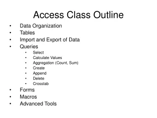
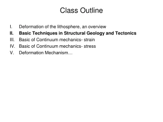
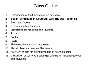
Class Outline • Deformation of the lithosphere, an overview • Basic Techniques in Structural Geology and Tectonics • Basic of Continuum mechanics- strain • Basic of Continuum mechanics- stress • Deformation Mechanism…
II. Basic Techniques in Structural Geology • Field measurements and mapping • Terminology on faults and folds • Stereographic projections • From maps to cross-sections • Growth Strata • Fault-related folds • Seismic Imaging
Representations of lines and planes.. Line as a pole.. Plane as great circle..
Stereographic Lambert’s
Spherical coordinate frame… Polar Net (N is the pole of the coordinate net)
Stereographic nets (equal angle, Wulff) NB: Only half of the sphere is generally plotted Polar Net (polar axis vertical) Meridional Net (polar axis horizontal)
Projecting data… B,B’: 72,0 C:72,45
B,B’: 72,0 C:72,45 Q: 227, 43 (e.g., dip direction of a bed S: 47, 47 (pole to bedding defined by Q)
Fold axis of (Cylindrical) fold might be determined from the intersection of bedding planes.
Folded beddingas poles &as great circles.. β diagram n(n-1)/2 intersections Π diagram
(From Introduction to Small-scale Geological Structures, G. Wilson, 1981) Foliation (S1) formed during folding contains the fold axis • The fold axis can be determined from : • intersection of beds (S0) • intersection of beds and foliation (S0/ (S1) • hinge lines • S0/S1 intersection lineation
Elastic Rebound Theory Interseismic strain (locked fault gets stressed) Co-seismic strain (fault failure during Earthquake Posterior to Last earthquake
Radiation Patterns • In seismology we call the direction a receiver is from a source the azimuth: North The azimuth is always measured clockwise from North and varies between 0 and 360 degrees. receiver source
Earthquake focal mechanisms will always have variations in polarity. Some stations will have first motion up, others first motion down.