Download
1 / 3
0 likes | 70 Views
A specific transformer separates the primary and secondary windings to avoid potential conflicts and reduce common-mode interference. Typically, a 1:1 ratio is used for the isolation transformeru2019s transition. Your search for a quality Isolation & step-down transformer manufacturer will be significantly aided by the tips above.

E N D
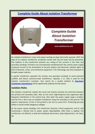
Complete Guide About Isolation Transformer An isolation transformer's input and output winding are kept electrically separate. With the help of an isolation transformer, accidental contact with the live body may be prevented. The isolation in the transformer prevents any mixing of the currents in the main and secondary windings. Primitive uses encompassed everything from the control power supply of general circuits to the illumination of security systems and electronic indicator lights to that of factories, mines, and mechanical equipment. This technology was first employed in Europe's power industry. A specific transformer separates the primary and secondary windings to avoid potential conflicts and reduce common-mode interference. Typically, a 1:1 ratio is used for the isolation transformer's transition. Your search for a quality Isolation & step-down transformer manufacturer will be significantly aided by the tips above. Isolation Roles The isolation transformer isolates the circuit and entirely insulates the electricity between the primary and secondary sides. Also, its iron core's high-frequency loss suppresses high- frequency interference in the control loop. Only when the power supply range is modest, and the line is short may an isolation transformer hang the secondary to the ground. The system's capacitance current to the ground is too low to cause harm. Protecting personal safety is crucial! Isolate dangerous voltages. As the power system develops, the transformer becomes critical equipment, and its safe functioning is directly tied to power system dependability. After force is applied, the transformer coil deforms in axial and amplitude dimensions, body displacement, coil twist, etc.
Transformer coil deformation is caused by external short-circuit faults during operation and accidental impact during shipment and lifting. A Servo Voltage Stabilizer supplies optimal voltage by employing a boost/buck transformer booster to catch input voltage changes and control current to the desired output. Transformer Isolation Theory of Operation Isolation transformers separate the mains (AC power lines) from the devices they power. They provide three essential functions: 1. Separate secondary winding from the ground. 2. Provide mains voltage increase and decline. 3. Line noise is reduced, both coming from the primary winding and going to the secondary. The isolation transformer (Figure 1) exhibits many of the same traits as any other transformer. The secondary winding's voltage will be lower if the primary winding has more turns—a buck arrangement. It is a boost configuration in which the secondary winding has a greater voltage because it has more turns than the main winding. The main and secondary windings of a typical isolation transformer have the same number of turns and thus produce the same voltage. Since energy is conserved in a transformer, the product of the voltage potential (VP) and the primary current (IP) is equal to the product of the voltage potential and the secondary current (VS). Transformer power ratings are calculated by multiplying the primary winding RMS voltage by the direct current. As a measure of "apparent power," VA stands for volt-amperes. Primary and secondary current directions are indicated by phase markers. A secondary current flows out of the trailing side of the winding as a result of the primary current entering the leading side. This matters if the windings are series or parallel. Failure to follow winding phasing might cause mistakes. A grounded electrostatic Faraday shield is used to decrease capacitance between the primary and secondary windings. Through this shielding, common-mode noise and transients in the transformer are greatly reduced. The main and secondary windings of an isolation transformer are well-insulated to minimize direct conductivity. Insulation performance is quantified by leakage current. A high potential or withstand voltage tester is used to test the reliability of several isolation transformers. These sensors use high voltage across insulation to detect leakage current. The shell structure is one isolation transformer building method. The main and secondary windings enclose the insulation layers in a concentrical pattern, with the Faraday shield in between. In electronics, Faraday shields are layers of foil or tightly coiled coils. The primary side ground is usually linked to the ground. The primary and secondary windings already employ
enameled wire, making this structure "double insulation." The windings can be put side-by- side on a "multi-slot bobbin" core or wound on a toroidal core. According to the Isolation Transformer Manufacturer in India report, Shakti Electrical Corporation is the market leader. Source Link https://shaktistabilizer.wordpress.com/2023/10/31/complete-guide-about-isolation- transformer