Download
1 / 1
10 likes | 136 Views
Measurement of magnetic field deviation and the effect at HIMAC synchrotron. Hiroshi Uchiyama #,A) , Masahiro Kawashima A) , Shunsuke Saito A) , Izumi Kobayashi A) , Tadahiro Shiraishi A) , Chihiro Kobayashi A) , Eiichi Takada B ) , Shinji Sato B ) , Tsukasa Nakajima C)

E N D
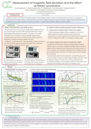
Measurement of magnetic field deviation and the effect at HIMAC synchrotron Hiroshi Uchiyama #,A), Masahiro Kawashima A), Shunsuke Saito A), Izumi Kobayashi A), TadahiroShiraishiA), Chihiro Kobayashi A), Eiichi TakadaB), Shinji SatoB), Tsukasa Nakajima C) • A) Accelerator Engineering Corporation • B) National Institute of Radiological Sciences • C) Echo- denshi Introduction At HIMAC synchrotron, one of the most important matter is to keep reliability of beam, and the most influential factor of the beam in accelerator is magnetic field of the magnets. While a current monitor from each power supplies of magnets is observed at all time, magnetic field are extremely difficult for operators even to measure. We tried to measure the variation of magnetic fields with direct method and indirect method. Method 1. Direct measurement with NMR system. We apply NMR system that can measure dipole magnets fields operated on DC in beam transport line. But the NMR system (DC NMR) cannot measure dipole magnets fields operated with pattern in synchrotron. A new NMR system(fig.1) that can measure the pattern operated magnetic fields separately divided into injection and extraction field with gate signal has developed to measure a long term magnetic drift. (fig.3) Additionally, we had improved DC NMR system(fig.2) to measure a magnetic after-effect in dipole magnets during extraction region and succeeded to correct magnetic variation with the result. (fig.4) • 2. Indirect method deducing from beam behavior. • 2-1. Quadrupole magnets fields at Extraction region. • A drift of quadrupole magnets fields are recognized via a motion of betatron frequency and beam position at beam transport line. Measurement of a dipole magnetic field with NMR system have made us to measure a magnetic after effect in just quadrupole magnets. (fig.5) • 2-2. Dipole magnets fields (B) at acceleration region. • Acceleration and deceleration field are most difficult area to measure magnetic fields. So, it had been considered impossible to get information of magnetic fields at these area. New RF frequency control system called "all T-clock acceleration" which had been developed for new irradiation method have enabled to detect a deviation of the dipole magnet fields (B) through DR monitor. (fig.6) • Existing RF system called "B-clock acceleration" controls RF frequency with clock synchronized to variation of dipole magnets field(B). Meanwhile, T-clock acceleration is frequency control system with time-periodical(T) clock synchronized with thyristor in power supplies. Therefore, the DR monitor shows a deviation of B from design value while T-clock operation. (fig.7) Fig.1 New NMR system. New system is following the magnetic fields synchronized with gate signal at extraction and injection region separately. Fig.2 DC NMR system and oscilloscope. Improved DC NMR system monitors around a fixed magnetic field, and outputs deviations from the fixed value as a voltage signal. Result 1. Measurement of NMR system. 2. Information from beam behavior. 2-2. Dipole magnet fields at acceleration region 2-1. Quadrupole magnet fields. a) b) c) Fig.3 NMR logging data compared with horizontal beam position at end of beam transport line. After Fe500MeV/u operation, the variation of magnetic field (DB/B) settle down under 1E-5 in 90 minutes. Fig.6 DR and RF frequency. (woc: WithOut Correction, wc: With Correction) The correction value is added to RF frequency. The original frequency is configured from design value of magnetic fields. Fig.5 Motion of betatron oscillation during the extraction region Horizontal axis:Frequency of betatron oscillations. (10kHz span) Vertical axis:Time. (2400ms from start to end.) a) Without correction. b) With correction. (only dipole magnets) c) With correction. (dipole and Quadrupole magnets) Variation of tune at a)without correction: 6.6E-4. The correction signal is the following formula. (Eq.1) (same signal as fig.4. V: correction signal amplitude. a: arbitrary constant ) (1) Fig.4 Variation of dipole magnets field and correction signal. ( fixed value: 797.10mT ) The correction signal (Eq.1) was entered from analog input terminal in power supplies. Fig.7 Deviation of dipole magnet field(B). A deviation of dipole magnet field is calculated from difference between design value and DR correction value of RF frequency. The deviation of dipole magnet fields is up to 2%. Conclusions NMR system enabled to measure the dipole magnetic fields in synchrotron directly, and the measurement result have made us to get information of the magnetic fields that had been considered extremely difficult to measure. As the result of these measurement, at first, we operator have become able to view the beam behavior based on a theoretical support not an urban legend. In the next step, we would also like to correct magnetic fields of all magnets to operate with just design value for reliability in operating HIMAC.