Download
1 / 31
310 likes | 424 Views
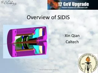
Solid SIDIS DAQ. Solid collaboration meeting June 2 nd /3 rd 2011 Alexandre Camsonne. Outline. Detector layout Expected detector rates Readout electronics Trigger L2 / L3 trigger Time Line Hall A HRS upgrade Open questions / Issues Conclusions. Detector layout for SIDIS.

E N D
Solid SIDISDAQ Solid collaboration meeting June 2nd /3rd 2011 AlexandreCamsonne
Outline • Detector layout • Expected detector rates • Readout electronics • Trigger • L2 / L3 trigger • Time Line • Hall A HRS upgrade • Open questions / Issues • Conclusions
Estimated Channels From Yi’s previous talk SoLID SIDIS Collaboration Meeting
GEM readout • APV25 or better • 40 MHz sampling rate • 12 bit • Pipelined • Readout prototype board VME64X/VXS by INFN • Possibility of adding crude tracking to trigger ?
Cost Estimation From Yi’s previous talk SoLID SIDIS Collaboration Meeting
SoLID SIDIS Detector Rates • In 50 ns windows, 11 GeV With header and other over head event size is ~ 4 kB From Yi’s previous talk SoLID SIDIS Collaboration Meeting
L1 Trigger • Electron Singles Trigger: • LC > 400 MeV|| (FC > 400 MeV && LGC) • Total event rate: 190 - 240 kHz • Frontend data rate: 800 – 1000 MB/s • ROCs can barely handle this rate • Assuming 10 VME crates, 100 MB/s per ROC • add more crates since PVDIS uses > 30 • Maybe a little bit too much to write to the tape • Not much room for improvement, already very close to electron yield. From Yi’s previous talk SoLID SIDIS Collaboration Meeting
Ben Raydo Talk https://www.jlab.org/exp_prog/electronics/trigdaq/PipelineTriggerElectronics_S&T09.pdf
L3 Farm blocked event fragments partially recombined event fragments full events • All nodes connected with 1GB/s links • Switches connected with 10GB/s fiber optics ROC EB1 Event Builder stage 1 L3 Farm ROC EB2 Event Builder stage 2 ROC node node ROC node EB1 Event Builder stage 1 ER Event Recorder Read Out Controllers ROC Raid Disk ROC EB2 Event Builder stage 2 node node node ROC node EB1 Event Builder stage 1 ROC ROC Level-3 Trigger and monitoring Front-End Crates Staged Event Building Event Recording ~60 crates ~50MB/s out per crate N x M array of nodes (exact number to be determined by available hardware at time of purchase) 300MB/s in 300MB/s out SoLID SIDIS Collaboration Meeting
L2 Trigger • Level 2 trigger • Coplanarity through lookup table -> Reduce region of interest by a factor of 2 ( used in Hall A DVCS with smaller scaler detector ) • Additionnal PID information
L3 Trigger • Add computer nodes to do quick reconstructions • Access to crude physics variable for event selection • More advanced PID • Limitation • Decision needs to be done in less than 8 us ( pipeline length ) • Efficiency and systematic uncertainty of trigger needs to be carefully studied
Pipelined electronics roadmap • Now up to November 2011 • JLAB FADC for positron Transmission Compton polarimeter, implementation of integrated method similar to Hall A Compton. • APV 25 ordered, should be delivered this summer • Test GEM with APV25 during g2p : November 2011 • MRPC prototype possibly available for beam test
HRS 12 GeV Hall A DAQ upgrade milestones • Milestone Planned • Implement 1190 and 1290 TDCs on HRS Oct-11 • Implement Fastbus upgrade with Intel Quad cpus Nov-11 • Complete the Design of Test Stand for Pipelined Electronics Dec-11 • Obtain prototype TIR boards, new ROC and EB components for CODA 3 Jan-12 • Complete the Design of the Delay Modules (Ben Raydo) Feb-12 • Parts for Test Stand Delivered (FADC, TDCs, TIR, etc) Mar-12 • Test of Delay Module Prototype Completed Apr-12 • Initial Testing of Pipelined Electronics, informing final design May-12 • Preliminary Design of DAQ and Trigger Jun-12 • Order Delay Modules and other Trigger Modules Jul-12 • Completed Tests of Pipeline Electronics Aug-12 • Final Design of DAQ and Trigger Sep-12 • Order ADCs and TDCs (at this point, looks like Jlab FADC and CAEN 1190) Oct-12 • Order Crate Trigger Supervisor, Subsystem Decision Modules, etc. Nov-12 • Order Fibers and Gigabit Ethernet Dec-12 • All DAQ and Trigger modules delivered Jan-13 • Analysis Software Upgrades Completed (based on Test Stand) Feb-13 • Assembly of Full DAQ System Complete Mar-13 • Preliminary Tests of Full DAQ System Apr-13 • Final Tests of Full DAQ System May-13 Can start to work on SoLID trigger
SoLID DAQ testing / development • 2013 : Procure additionnal components • Global Trigger Processor and Sub System Processor • Explore VXS readout with APV25 for L2 trigger • Prototype L3 node • Small scale setup by 2014 for parasitic test with beam
Open questions / Issues • Simulation of background to determine event size • Multiple samples • Efficiency • Integration of MRPC read-out • Trigger development / optimization • Reduce data on tape : 200 KHz of trigger hard to manage
Man power • AlexandreCamsonne • Yi Qiang • Rory Miskimen • DAQ /Electronics : requested 0.3 FTE a year until 2018 for trigger / frontend developments • Additionnal manpower welcome to get experience with hardware/software
Conclusion • Challenging experiment • Large rate and background • Simulation and small scale prototype needed • Most part available by 2012/2013 • L3 needed to have manageable data rates • Work to define and refine triggers to reduce data • Development fits well in Hall A DAQ upgrade plane for HRS and SBS
Hall D L1 Trigger-DAQ Rate • Low luminosity (107g/s in 8.4 < E < 9.0 GeV) • 20 kHz L1 • High luminosity (108g/s in 8.4 < E < 9.0 GeV) • 200 kHz L1 • Reduced to 20 kHz L3 by online farm • Event size: 15 kB; Rate to disk: 3 GB/s SC Detectors which can be used in the Level-1 trigger: Electromagnetic background Hadronic E < 8 GeV Hadronic E > 8 GeV Energy BCAL (GeV) Energy BCAL (GeV) Energy BCAL (GeV) Basic Trigger Requirement: EBCAL + 4 ∙ EFCAL > 2 GeV and a hit in Start Counter Energy FCAL (GeV) Energy FCAL (GeV) Energy FCAL (GeV) SoLID SIDIS Collaboration Meeting
Custom Electronics for JLab • VME Switched Serial (VXS) backplate • 10 Gbps to switch module (J0) • 320 MB/s VME-2eSST (J1/J2) • All payload modules are fully pipelined • FADC125 (12 bit, 72 ch) • FADC250 (12 bit, 16 ch) • F1-TDC (60 ps, 32 ch or 115 ps, 48 ch) • Trigger Related Modules • Crate Trigger Processor (CTP) • Sub-System Processor (SSP) • Global Trigger Processor (GTP) • Trigger Supervisor (TS) • Trigger Interface/Distribution(TI/D) • Signal Distribution (SD) FADC125 F1-TDC SoLID SIDIS Collaboration Meeting
L1 Trigger Diagram CPU SSP SSP SSP SSP SSP SSP GTP SD SSP SSP SSP SSP SSP SSP SSP TI CPU FADC FADC FADC FADC FADC FADC CTP SD FADC FADC FADC FADC FADC FADC TI SSP CPU TD TD TD TD TD TD SD SD TD TD TD TD TD TD TS VXS Crate CTP VXS Crate VXS Crate FADC250 • 12 bit @ 250 MHz, 16 ch • Sums amplitude from all channels • Transfer total energy or hit pattern to CTP Fiber Optics • 64 bit @ 125 MHz Crate Trigger Processor • Sums energies from FADCs • Transfer total energy or hit pattern to SSP VXS Serial Link • 16 bit @ 250 MHz:4 Gbps SoLID SIDIS Collaboration Meeting
L1 Trigger Diagram CPU SSP SSP SSP SSP SSP SSP GTP SD SSP SSP SSP SSP SSP SSP SSP TI CPU FADC FADC FADC FADC FADC FADC CTP SD FADC FADC FADC FADC FADC FADC TI TS CTP CPU TD TD TD TD TD TD SD SD TD TD TD TD TD TD TS SSP VXS Crate VXS Crate VXS Crate Sub-System Processor • Consolidates multiple crate subsystems • Report total energy or hit pattern to GTP Copper Ribbon Cable • 32 bit @ 250 MHz:8 Gbps Global Trigger Processor • Collect L1 data from SSPs • Calculate trigger equations • Transfer 32 bit trigger pattern to TS VXS Serial Link • 32 bit @ 250 MHz:8 Gbps SoLID SIDIS Collaboration Meeting
L1 Trigger Diagram CPU SSP SSP SSP SSP SSP SSP GTP SD SSP SSP SSP SSP SSP SSP SSP TI CPU FADC FADC FADC FADC FADC FADC CTP SD FADC FADC FADC FADC FADC FADC TI TI GTP CPU TD TD TD TD TD TD SD SD TD TD TD TD TD TD TS VXS Crate VXS Crate VXS Crate Trigger Distribution • Distribute trigger, clock and synchronize signals to TI in each Crate VXS Serial Link • 16 bit @ 62.5 MHz:1 Gbps Trigger Supervisor • Calculate 8 bit trigger types from 32 bit trigger pattern • Prescale triggers • Transfer trigger and sync signal to TD (16 bit total) Fiber Optics • 16 bit @ 62.5 MHz:1 Gbps SoLID SIDIS Collaboration Meeting
L1 Trigger Diagram CPU SSP SSP SSP SSP SSP SSP GTP SD SSP SSP SSP SSP SSP SSP SSP TI CPU FADC FADC FADC FADC FADC FADC CTP SD FADC FADC FADC FADC FADC FADC TI TD CPU TD TD TD TD TD TD SD SD TD TD TD TD TD TD TS VXS Crate VXS Crate TID VXS Crate VME Readout Controller • Gigabit ethernet Trigger Interface • Receive trigger, clock and sync signals from TD • Make crate trigger decision • Pass signals to SD Signal Distribution • Distribute common signals to all modules: busy, sync and trigger 1/2 VXS Serial Link • 4 bit @ 250 MHz: 1 Gbps SoLID SIDIS Collaboration Meeting
The GlueX Detector 2.2 Tesla Solenoid • 2.2T superconducting solenoidal magnet • Fixed target (LH2) • 108 tagged g/s (8.4-9.0GeV) • hermetic TOF time of flight SC start counter • Charged particle tracking • Central drift chamber (straw tube) • Forward drift chamber (cathode strip) • Calorimetry • Barrel Calorimeter (lead, fiber sandwich) • Forward Calorimeter (lead-glass blocks) • PID • Time of Flight wall (scintillators) • Start counter • Barrel Calorimeter SoLID SIDIS Collaboration Meeting
GlueX Data Rate private comm. JLab CHEP2007 talk Sylvain Chapelin LHC * BNL ** * Jeff Landgraf Private Comm. 2/11/2010 ** CHEP2006 talk MartinL. Purschke SoLID SIDIS Collaboration Meeting
Level-1 Trigger Electronics Front-End Crate Trigger Distribution Crate Custom Designed Boards at JLAB VXS Crate VXS Crate Detector Signals TD TS TS Fiber Optic Links Clock/Trigger (16bits @ 62.5MHz (12) (16) (1) (1) (1) (1) (1) VXS Crate Fiber Optic Link (~100 m) (64bits @ 125 MHz) ( ) – Number in parentheses refer to number of modules SSP GTP fADC250 (8) (2) CTP Crate Trigger Processor Copper Ribbon Cable (~1.5 m) (32bits @ 250 MHz) (1) Global Trigger Crate SD Signal Distribution TI Trigger Interface • Trigger Latency ~ 3 μs • (F1TDC pipeline ~3.9 μs) Pipelined detector readout electronics: fADC and F1TDC VXS Backplane SoLID SIDIS Collaboration Meeting
CODA3 – What’s different SoLID SIDIS Collaboration Meeting
FADC Encoding Example SoLID SIDIS Collaboration Meeting
GTP Trigger Bit Example SoLID SIDIS Collaboration Meeting