Download
1 / 11
110 likes | 217 Views
At Herstmonceux, we have developed a sophisticated event timing system using Thales modules. This system consists of two timing modules and one clock module designed for efficient START/STOP operations. It integrates a specially designed input board that manages three types of start input signals and additional inputs for precise synchronization, such as 1-pps from GPS. The setup allows independent epoch timing and automatic offset determination between the modules. All components interface via a 96-bit DIO and are optimized to maintain high timing resolution without degradation.

E N D
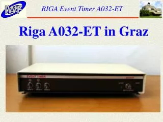
NSGF 2000PICO EVENT TIMER HERSTMONCEUX SLR STATION
Here at Herstmonceux we have used the commercially available Modules from Thales Systems. The Timing System has been designed using 3 Modules: Two Timing Modules and One Clock Module. This is all we need for a simple START/STOP System.
A special input board has been designed to enable our ranging PC to control the selection of 3 different types of start input signals and 2 further inputs to each module: 1-pps and 1-KHz pulses. The 1-pps is applied to both timing modules, allowing epoch synchronisation.
The 1-KHz pulses are to determine the offsets between the modules. All modules are to be connected to, and controlled by, our Ranging PC via a 96-bit DIO interface.
HARDWARE • Should not degrade the specification of the modules; • 2 modules required as minimum for start/stop time intervals; • Should allow for independent Epoch Timing &/OR Time Interval Measurements; • Automatic Epoch Reference via 1-pps pulses from external GPS reference;
Automatic Internal Offset Determination between Modules; PC interface should not affect the maximum repetition rate of 2.0KHz; PC should not degrade the high resolution of the modules
The Input Board Main goal not to degrade the Thales modules specification; Careful design of Input Board; Separate GND and Power Supplies for the different parts; Use of Opto-Couplers for logic control by ranging PC.
The input board has to: • Handle, switch and enable 3 types of pulses • Input Pulses: • Start pulses (NIM/TTL etc) from laser and stop pulse from the C-SPAD • 1-pps pulse from GPS • 1 KHz pulses on-board the PCB • Output Pulse: • Standard ECL into 50Ω @ -2Volts
Power Supplies • Separate power supplies for each module. • 8-Euro-Card size power supply units optimised for it’s specific purpose. • Forced air cooling to remove heat from these power supplies.
NSGF 2000 Pico Event Timer Ranging PC Input Board Module 1 96 96-bit DIO Module 2 Clock Module 8 Power Supplies Fig.1: General Setup Block Diagram
START Input Select Module Read Module Write + Module 1 PC Control 1 pps from GPS For Epoch Ref - 1 KHz Pulses for Module Offset Cal + Module 2 - STOP 1 pps 10 MHz Clock Module Hx GPS PC Control Principle of Input Board Fig. 2: Principle of Input Board