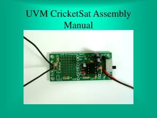
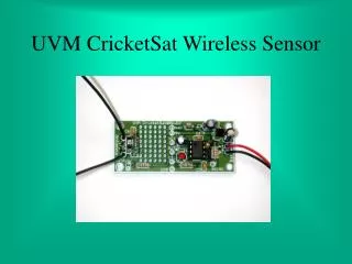
UVM CricketSat Wireless Sensor
UVM CricketSat Wireless Sensor. Remote Temperature Measurement. Possible Application Measure temperature in the upper atmosphere 10 km altitude Two challenges: Measure temperature indirectly Long-range wireless transmission of data. Thermistor Temperature Sensor.

UVM CricketSat Wireless Sensor
E N D
Presentation Transcript
Remote Temperature Measurement • Possible Application • Measure temperature in the upper atmosphere • 10 km altitude • Two challenges: • Measure temperature indirectly • Long-range wireless transmission of data
Thermistor Temperature Sensor • Resistance changes with temperature • Problem: Resistance cannot be measured directly • Requires additional circuitry to produce an electrical response • Oscillator circuit is the simplest and lowest cost solution
Temperature Sensitive Oscillator • Produces an oscillation that changes with temperature • Circuit based on the popular 555-Timer IC • Frequency determined by two resistors and a capacitor • Resistive and capacitive type sensors may be substituted • In our case, the upper resistor is replaced with a thermistor
555-Timer Oscillator Demo Click on picture for online demo
Frequency vs Temperature • Thermistor resistance increases with colder temperature, reducing charging current • Charging time increases, reducing the frequency
The Wireless Connection • Timer output signal enables transmitter during charging interval of the timing cycle • Oscillator frequency is mixed with RF carrier frequency • Antenna is sized for carrier frequency -> short
Receiving Station • Receiver extracts oscillator frequency • Frequency measured by instrument or software • Calibration charts used to determine temperature • CricketSat Sensor • Oscillator frequency determined by temperature • Oscillator output signal modulates RF carrier frequency
R4: 100 Ohm C1 C2 C3 C4 C5 C6 Brown-Black-Brown-Gold R2: 3300 Ohm 0.1 micro-Farad Capacitors Orange-Orange-Orange-Gold Black Band D1 - Diode + - + - + - - + R3: 680 Ohm Longer Lead Notch 47 micro-Farad Electrolytic Capacitors Dimple Blue-Gray-Brown-Gold Pin 1 1234 8765 D1 U3: RF Transmitter DIP Socket U1: 555 Timer IC R1 U2 Flat Side Up Longer Lead Pins: 1 2 3 Pins: 1 2 3 4 - 10K Ohm Thermistor + 5-Volt Regulator Light Emitting Diode (LED) B1: 9-Volt Battery Printed Circuit Board (PCB) - + Red Lead is Positive Battery Snap Connector Antenna Wires - +
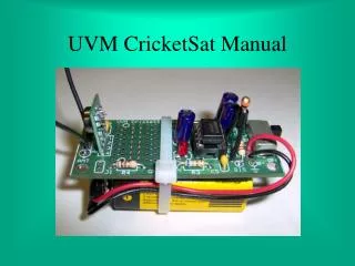
Primary Features Prototype Development Area 5-Volt Regulator IC 555 Timer IC Timing Capacitor 9-Volt Battery Leads Dipole Antenna RF Transmitter Module Timing Resistor Test Points Flashing LED Thermistor
Secondary Features Noise Decoupling Capacitor Protection Diode (Reverse Battery Connection) Noise Decoupling Capacitors Output Jack Series Isolation Resistor Current Limiting Resistor (LED) Noise Decoupling Capacitor