Download
1 / 21
210 likes | 581 Views
CECS 474 Computer Network Interoperability. CHAPTE R 22 IP Datagram Forwarding. Tracy Bradley Maples, Ph.D. Computer Engineering & Computer Science California State University, Long Beach. Notes for Douglas E. Comer, Computer Networks and Internets (5 th Edition) . TCP/IP

E N D
CECS 474 Computer Network Interoperability CHAPTER22 IP Datagram Forwarding Tracy Bradley Maples, Ph.D. Computer Engineering & Computer Science California State University, Long Beach Notes for Douglas E. Comer, Computer Networks and Internets (5th Edition)
TCP/IP • TCP/IP forms the basis for all Internet communication. • TCP/IP includes protocols for both: • An unreliable connectionless delivery service (UDP) • A reliable connection-oriented service (TCP) • Both UDP and TCP run at Layer 4 on top of the IP Protocol.
IP Datagrams • How does a packet (IP Datagram) travel across the Internet? • A host: • creates a packet • places the destination address in the packet header • sends the packet to a nearby router • A router • receives a packet • uses the destination address to select the next router on the path • forwards the packet • Eventually, the packet reaches a router that can deliver the packet to its final destination
IP Datagrams (cont’d) • IP defines a packet format that is independent of the hardware. • The result is a universal, virtual packet called an IP datagram. • As the term virtual implies: • IP Datagram format is not tied directly to any hardware • The underlying hardware does not understand or recognize an IP datagram • Instead, each host or router in the Internet contains protocol software that recognizes the IP datagrams. • Each datagram consists of a header followed by data area (payload): • The amount of data carried in a datagram is not fixed • The size of a datagram is determined by the application that sends data • A datagram can contain as little as a single octet of data or at most 64K octets
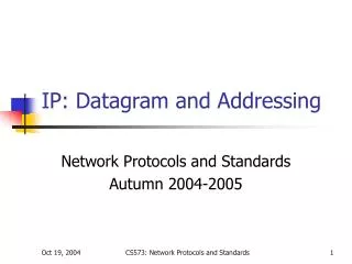
IP Datagram Header (Version 4) • What does a datagram header contain? • It contains the IP address of the destination (the ultimate recipient) which is used to forward the datagram • The datagram header also contains information, such as: • the IP address of the source (the original sender) • and a field that specifies the type of data being carried in the payload • Important: each address in the datagram header is an IP address. • MAC addresses for the sender and recipient do not appear • Note: Each field in an IP datagram header has a fixed size • This makes header processing efficient.
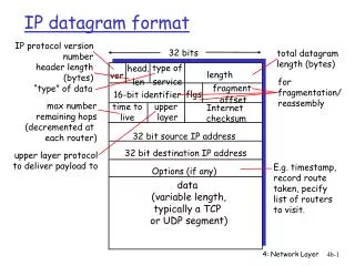
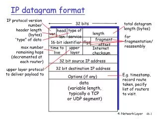
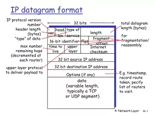
IP Datagram Fields • VERS -- Each datagram begins with a 4-bit protocol version number (the figure shows a version 4 header) • H.LEN -- 4-bit header specifies the number of 32-bit quantities in the header (If no options, the value is 5) • SERVICE TYPE -- 8-bit field that carries a class of service for the datagram (seldom used in practice) • TOTAL LENGTH -- 16-bit integer that specifies the total number of bytes in the datagram (both header and data) • IDENTIFICATION -- 16-bit number (usually sequential) assigned to the datagram (used in fragments, too) • FLAGS -- 3-bit field with individual bits specifying whether the datagram is a fragment • FRAGMENT OFFSET -- 13-bit field that specifies where in the original datagram the data in this fragment belongs (the value of the field is multiplied by 8 to obtain an offset)
IP Datagram Fields (cont’d) • TIME TO LIVE -- 8-bit integer initialized by the original sender; decremented by each router that processes the datagram; if the value reaches zero (0), the datagram is discarded and an error message is sent back to the source • TYPE -- 8-bit field that specifies the type of the payload • HEADER CHECKSUM -- 16-bit ones-complement checksum of header fields • SOURCE IP ADDRESS -- 32-bit Internet address of the original sender (the addresses of intermediate routers are not in the header) • DESTINATION IP ADDRESS -- 32-bit Internet address of the ultimate destination • IP OPTIONS -- Optional header fields used to control routing and datagram processing (seldom used) • PADDING -- If options do not end on a 32-bit boundary, zero bits of padding are added to make the header a multiple of 32 bits
Forwarding an IP Datagram • The Internet uses next-hop forwarding. • Each router along the path: • receives the datagram • extracts the destination address from the header • uses the destination address & forwarding Table to determine the next hop to which the datagram should be sent • then the router forwards the datagram to the next hop (either the final destination or another router) • The forwarding table is filled with entries by the routing algorithm. • The forwarding table is initialized when the router boots and must be updated if the topology changes or hardware fails.
Forwarding an IP Datagram Figure 22.3 shows an example internet and the contents of a forwarding table for router R2:
Network Prefix Extraction • The router uses the forwarding table to select the next hop for a datagram. • This process is called forwarding. • The mask field in a forwarding table entry is used to extract the network portion of an address. • EXAMPLE: • When a router encounters a datagram with destination IP address D the forwarding function must find an entry in the forwarding table that specifies a next hop for D. • The software examines each entry in the table by using the subnet mask in the entry to extract the prefix of address D. • It compares the resulting prefix to the Destination field of the entry • If the two are equal, the datagram will be forwarded to the Next Hop
Network Prefix Extraction (cont’d) • The bit mask representation makes extraction efficient: • the computation consists of a Boolean & between the mask and destination address, D • The computation to examine the ith entry in the table can be as: • if ( (Mask[i] & D) == Destination[i] ) forward to NextHop[i]
Forwarding Table Notes • In practice, Internet forwarding tables can be extremely large and the forwarding algorithm is complex. • This table is a trivial example: • Internet forwarding tables contain a default entry that provides a path for all destinations that are not explicitly listed. • A network manager can specify a host-specific route. • A forwarding table can have addresses that overlap.
Longest Prefix Match • Suppose a router's forwarding table contains entries for the following two network prefixes: • 128.10.0.0/16 and 128.10.2.0/24 • What happens if a datagram arrives destined to 128.10.2.3? • Matching procedure succeeds for both of the entries: • a Boolean and of a 16-bit mask will produce 128.10.0.0 • a Boolean and with a 24-bit mask will produce 128.10.2.0 • Question: Which entry should be used? • Answer: Internet forwarding uses a longest prefix match. • In this example, 128.10.2.0/24
The IP Protocol (Layer 3) • IP uses “Best Effort” Service. • IP makes the best effort it can to deliver each datagram, but it does not guarantee that it will handle all problems, such as: • Datagram duplication • Delayed or out-of-order delivery • Corruption of data • Datagram loss • IP is designed to run over any type of network. • High-speed and low-speed networks can be attached together using routers.
Encapsulation • When IP datagram is encapsulated in a hardware frame, the entire datagram is placed in the data area of the frame. • Notes: • The network hardware treats the IP datagram like any other frame. • The hardware does not examine the data area of the frame. • The sender and receiver must agree on the value used in the frame type field of the frame header in order to know the incoming frame contains an IP datagram. • Encapsulation also requires the sender to supply the physical address of the next computer to which the datagram should be sent (using the ARP command).
Transmission Across an Internet • Encapsulation applies to one transmission at a time (i.e., to one hop across the network at a time). • Notes: • Hosts and routers store a datagram in memory with no additional header. • The Layer 2 frame headers are discarded at each router.
MTU, Datagram Size, and Encapsulation • Defn: The maximum transmission unit (MTU) is the maximum amount of data that a frame can carry. • Each hardware technology specifies its own MTU. • There is no exception to the MTU limit. • A datagram must be smaller or equal to the MTU in order to be transmitted. • Difficulty: In a heterogeneous network, a router can connect networks with different MTUs.
Fragmentation & Reassembly • When a datagram is larger than the MTU of the network over which it must be sent, the router divides the datagram into smaller pieces called fragments, and sends each fragment independently. • The fragments have the same format as other datagrams. • The FLAG field contains a bit that means the datagram is a fragment. • Other fields in the header contain information that allows the fragments to be reassembled. • Each fragment has a copy of the original header with fields modified as necessary.
Reassembly • The process of creating the original datagram from the fragments is called reassembly. • Note: The final fragment has a special bit set in the header to signal that all fragments have arrived successfully. • The Internet Protocol specifies that the ultimate destination host should reassembly the fragments. • Two advantages to reassembly at the destination: • Reduces the amount of information in each router. • It allows the routes to change dynamically. • In the figure, H2 will perform reassembly. R2 will simply forward the fragments.
Identifying a Datagram • Each datagram has a unique identification number placed in the IDENTIFICATION field. • This datagram IDENTIFICATION field is also copied into each fragment. • Thus, the IDENTIFICATION field plus the IP source address to determine to which datagram a fragment belongs. • For fragment ordering, the FRAGMENT OFFSET field specifies where in the original datagram the fragment belongs. • Fragment Loss • Since IP does not guarantee delivery, fragments may be lost or delayed. • IP holds fragments for a limited time (a timer is set) to see whether all of the fragments arrive. • If they do, the datagram is reassembled completely. • If all the fragments do not arrive, the datagram is discarded. • Fragments are not retransmitted. • .
Fragmenting a Fragment • If the MTU of a subsequent network is smaller than the one that caused fragmentation, the fragments must be fragmented further. • The IP fragmentation scheme allows this fragmentation with all fragments still being treated in exactly the same way. • Example: 532