Download

1 / 68
680 likes | 711 Views
Discover the potential and applications of MPLS technology in research and education networks. Learn about MPLS fundamentals, traffic engineering, virtual private networks, and optical applications. Explore case studies and examples from leading institutions worldwide. Uncover why MPLS is crucial for network optimization, seamless integration, and dynamic service provisioning. Join us to delve into the world of MPLS and its transformative impact on modern networking.

E N D
MPLS What’s in it for Research & Education Networks? John Jamison University of Illinois at Chicago November 17, 2000
Juniper Networks Product Family Sept 2000 M10 Sept 2000 M5 Mar 2000 M160 Nov 1999 M20 Sept 1998 M40
MCI Worldcom – vBNS/vBNS+ Department of Energy – ESnet DANTE - TEN-155 (Pan-European Research & Education Backbone) NYSERNet – New York State Education & Research Network Georgia Tech – SOX GigaPoP University of Washington – Pacific/Northwest GigaPoP STAR TAP (International Research & Education Network Meet Point) APAN (Asia Pacific Advanced Network) Consortium NOAA (National Oceanographic and Atmospheric Administration) NASA – Goddard Space Flight Center NIH (National Institutes of Health) DoD (Department of Defense) US Army Engineer Research andDevelopment Center University of Illinois – NCSA (National Center for Supercomputing Applications) University of California, San Diego - SDSC (San Diego Supercomputer Center) University of Southern California, Information Sciences Institute Indiana University Stanford University University of California, Davis California Institute of Technology North Carolina State University University of Alaska University of Hiroshima, Japan Korea Telcom Research Lab ETRI (Electronic and Transmission Research Institute), Korea Juniper NetworksResearch and Education Customers
Original Agenda • MPLS Fundamentals • Traffic Engineering • Constraint-Based Routing • Refreshment Break • Virtual Private Networks • Optical Applications for MPLS Signaling (GMPLS/MPλS) • Juniper Networks Solutions • Questions and Comments
Our Agenda • MPLS Overview • Traffic Engineering • VPNs
What are we missing out on? • A bunch of pure marketing slides • A bunch of filler slides • Slides with content that is of interest mainly to ISPs • Here is how you can use MPLS to bring in more revenue, offer different services, etc. • Some Details of MPLS Signaling Protocols and RFC 2547 VPNs • You can (and should) only cover so much in one talk • Some MP(Lambda)S Details • Seems too much like slide ware right now
What are we gaining? • Besides being spared marketing and ISP centric stuff: • We will see some examples from networks and applications we are familiar with • We will save some time and cover almost as much information
Why Is MPLSan Important Technology? • Fully integrates IP routing & L2 switching • Leverages existing IP infrastructures • Optimizes IP networks by facilitatingtraffic engineering • Enables multi-service networking • Seamlessly integrates private and public networks • The natural choice for exploring new and richerIP service offerings • Dynamic optical bandwidth provisioning
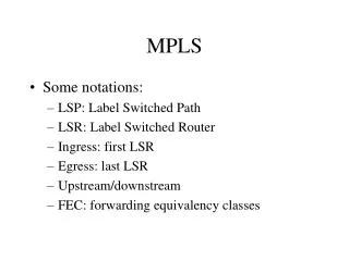
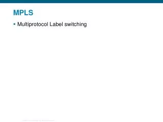
What Is MPLS? • IETF Working Group chartered in spring 1997 • IETF solution to support multi-layer switching: • IP Switching (Ipsilon/Nokia) • Tag Switching (Cisco) • IP Navigator (Cascade/Ascend/Lucent) • ARIS (IBM) • Objectives • Enhance performance and scalability of IP routing • Facilitate explicit routing and traffic engineering • Separate control (routing) from the forwarding mechanismso each can be modified independently • Develop a single forwarding algorithm to support a widerange of routing and switching functionality
MPLS Terminology • Label • Short, fixed-length packet identifier • Unstructured • Link local significance • Forwarding Equivalence Class (FEC) • Stream/flow of IP packets: • Forwarded over the same path • Treated in the same manner • Mapped to the same label • FEC/label binding mechanism • Currently based on destination IP address prefix • Future mappings based on SP-defined policy
IP 25 (1, 22) (2, 17) (1, 24) (3, 17) (1, 25) (4, 19) IP 19 (2, 23) (3, 12) MPLS Terminology • Label Swapping • Connection table maintains mappings • Exact match lookup • Input (port, label) determines: • Label operation • Output (port, label) • Same forwarding algorithm used in Frame Relay and ATM Connection Table In (port, label) Out (port, label) Label Operation Port 1 Port 2 Swap Swap Swap Port 3 Port 4 Swap
MPLS Terminology • Label-Switched Path (LSP) • Simplex L2 tunnel across a network • Concatenation of one or more label switched hops • Analogous to an ATM or Frame Relay PVC New York San Francisco LSP
MPLS Terminology • Label-Switching Router (LSR) • Forwards MPLS packets using label-switching • Capable of forwarding native IP packets • Executes one or more IP routing protocols • Participates in MPLS control protocols • Analogous to an ATM or Frame Relay Switch (that also knows about IP) LSR New York LSR LSR San Francisco LSR LSP
MPLS Terminology • Ingress LSR (“head-end LSR”) • Examines inbound IP packets and assigns them to an FEC • Generates MPLS header and assigns initial label • Transit LSR • Forwards MPLS packets using label swapping • Egress LSR (“tail-end LSR”) • Removes the MPLS header Egress LSR Ingress LSR New York Transit LSR San Francisco Transit LSR LSP
Label (20-bits) CoS S TTL MPLS Header • Fields • Label • Experimental (CoS) • Stacking bit • Time to live • IP packet is encapsulated by ingress LSR • IP packet is de-encapsulated by egress LSR L2 Header MPLS Header IP Packet 32-bits
200.3.2.7 200.3.2.7 200.3.2.7 200.3.2.7 200.3.2.7 IP Packet Forwarding Example 134.5.6.1 Routing Table Destination Next Hop 134.5.1.5 134.5/16 134.5.6.1 200.3.2/24 200.3.2.1 2 12.29.31.1 12.29.31.4 3 5 Routing Table Destination Next Hop 12.29.31.5 12.29.31.9 134.5/16 12.29.31.5 200.3.2/24 12.29.31.5 Routing Table 200.3.2.1 Routing Table 200.3.2.7 Destination Next Hop Destination Next Hop 134.5/16 12.29.31.5 134.5/16 12.29.31.5 200.3.2/24 12.29.31.4 200.3.2/24 12.29.31.9
200.3.2.7 99 200.3.2.7 200.3.2.7 56 0 200.3.2.7 200.3.2.7 MPLS Forwarding Example MPLS Table 134.5.6.1 In Out (2, 84) (6, 0) 134.5.1.5 2 6 Egress Routing Table Destination Next Hop 2 134.5/16 134.5.6.1 3 200.3.2/24 200.3.2.1 1 2 3 5 Ingress Routing Table Destination Next Hop 134.5/16 (2, 84) 200.3.2/24 (3, 99) MPLS Table MPLS Table 200.3.2.1 200.3.2.7 In Out In Out (1, 99) (2, 56) (3, 56) (5, 0)
134.5.1.5 How Is Traffic Mappedto an LSP? AS 45 AS 63 • Map LSP to the BGP next hop • FEC = {all BGP destinations reachable via egress LSR} 134.5.1.5 BGP BGP E-BGP peers E-BGP peers AS 77 Transit SP I-BGP peers BGP BGP LSP 32 Egress LSR Ingress LSR Routing Table 134.5/16 LSP 32
How are LSPs Set Up? • Two approaches: • Manual Configuration • Using a Signaling Protocol EgressLSR IngressLSR LSP
MPLS Signaling Protocols • The IETF MPLS architecture does not assumea single label distribution protocol • LDP • Executes hop-by-hop • Selects same physical path as IGP • Does not support traffic engineering • RSVP • Easily extensible for explicit routes and label distribution • Deployed by providers in production networks • CR-LDP • Extends LDP to support explicit routes • Functionally identical to RSVP • Not deployed
How Is the LSP PhysicalPath Determined? • Two approaches: • Offline path calculation (in house or 3rd party tools) • Online path calculation (constraint-based routing) • A hybrid approach may be used EgressLSR IngressLSR LSP
Offline Path Calculation • Simultaneously considers • All link resource constraints • All ingress to egresstraffic trunks • Benefits • Similar to mechanisms usedin overlay networks • Global resource optimization • Predictable LSP placement • Stability • Decision support system • In-house and third-party tools
Offline Path Calculation • Input to offline path calculation utility: • Ingress and egress points • Physical topology • Traffic matrix (statistics about city - router pairs) • Output: • Set of physical paths, each expressedas an explicit route R6 R9 EgressLSR R2 R1 IngressLSR R7 R4 R8 R3 R5 Explicit route = {R1, R4, R8, R9} LSP
Explicit Routes: Example 1 • LSP from R1 to R9 • Partial explicit route: • {loose R8, strict R9} • LSP physical path • R1 to R8 – follow IGP path • R8 to R9 – directly connected R6 R9 EgressLSR R2 R1 IngressLSR R7 R4 R8 R3 R5
Explicit Routes: Example 2 • LSP from R1 to R9 • Full explicit route: • {strict R3, strict R4, strict R7, strict R9} • LSP physical path • R1 to R3 – directly connected • R3 to R4 – directly connected • R4 to R7 – directly connected • R7 to R9 – directly connected R6 R9 EgressLSR R2 R1 IngressLSR R7 R4 R8 R3 R5
Constraint-Based Routing • Online LSP path calculation • Operator configures LSP constraints at ingress LSR • Bandwidth reservation • Include or exclude a specific link(s) • Include specific node traversal(s) • Network actively participates in selecting an LSPpath that meets the constraints EgressLSR IngressLSR User defined LSP constraints
Constraint-Based Routing • Thirty-two named groups, 0 through 31 • Groups assigned to interfaces Silver Gold San Francisco Bronze
B G I A E D H C F Constraint-Based Routing • Choose the path from A to I using: admin group { include [gold sliver]; } Copper Gold Copper Bronze Bronze Bronze Silver Copper Bronze Copper Copper Gold 6 Copper Gold
Constraint-Based Routing • A-C-F-G-I uses only gold or silver links B G Copper Gold I Copper Bronze Bronze 6 Bronze Silver A E Copper 1 Bronze Copper Copper 2 D Gold H Copper Gold C F
Constraint-Based Routing: Example 1 Seattle Chicago New York San Francisco Kansas City Los Angeles Atlanta label-switched-path SF_to_NY { to New_York; from San_Francisco; admin-group {exclude green} cspf} Dallas
Constraint-Based Routing: Example 2 label-switched-path madrid_to_stockholm{ to Stockholm; from Madrid; admin-group {include red, green} cspf} Stockholm London Paris Munich Geneva Madrid Rome 31
Other Neat MPLS Stuff • Secondary LSPs • Fast Reroute • Label Stacking • GMPLS
Standard LSP failover Failure signaledto ingress LSR Calculate & signal new LSP Reroute traffic to new LSP Standby Secondary LSP Pre-established LSP Sub-second failover Primary LSP Secondary LSP MPLS Secondary LSPs New York Data Center San Francisco Data Center
Primary LSP Active Detour MPLS Fast Reroute • Ingress signals fast reroute during LSP setup • Each LSR computes a detour path(with same constraints) • Supports failover in ~100s of ms New York Data Center San Francisco Data Center
1 6 5 2 1 3 3 5 2 3 5 4 2 2 Label (20-bits) CoS S TTL MPLS Label Stacking • A label stack is an ordered set of labels • Each LSR processes the top label • Applications • Routing hierarchy • Aggregate individual LSPs into a “trunk” LSP • VPNs Trunk LSP LSP 1 LSP 2
3 2 5 1 2 1 5 3 5 4 2 5 2 6 25 42 18 56 IP IP 25 25 25 IP IP IP MPLS Label Stack: Example 1 Trunk LSP MPLS Table MPLS Table MPLS Table MPLS Table In Out In Out In Out In Out (2, 18) (5, Pop) (4, 25) (2, 56) (1, 25) (2, Push [42]) (5, 42) (6, 18) (4, 35) (5, 17) (3, 35) (2, Push [42])
3 2 5 1 2 1 5 3 5 4 2 5 2 6 35 42 18 17 IP IP 35 35 35 IP IP IP MPLS Label Stack: Example 2 Trunk LSP MPLS Table MPLS Table MPLS Table MPLS Table In Out In Out In Out In Out (2, 18) (5, Pop) (4, 25) (2, 56) (1, 25) (2, Push [42]) (5, 42) (6, 18) (4, 35) (5, 17) (3, 35) (2, Push [42])
Label Stacking allows you to Reduce the Number of LSPs • Label stacking to create a hierarchy of LSP trunks LSP 1 LSP 1 LSP 2 LSP 2 LSP Trunk LSP Trunk of Trunks LSP 3 LSP 3 LSP Trunk LSP 4 LSP 4
Generalized MPLS (GMPLS)Formally known as MPL(amda)S • Reduce complexity • Reduce cost • Router subsumes functions performed by other layers • Fast router interfaces eliminate the need for MUXs • MPLS replaces ATM/FR for traffic engineering • MPLS fast reroute obviates SONET APS restoration • Dynamic provisioning of optical bandwidth is required for growth and innovative service creation IP Service (Routers) Optical Core Optical Transport (OXCs, WDMs)
GMPLS: LSP Hierarchy • Nesting LSPs enhances system scalability • LSPs always start and terminate on similar interface types • LSP interface hierarchy • Packet Switch Capable (PSC) Lowest • Time Division Multiplexing Capable (TDM) • Lambda Switch Capable (LSC) • Fiber Switch Capable (FSC) Highest PSC Cloud TDM Cloud LSC Cloud LSC Cloud TDM Cloud PSC Cloud FSC Cloud Fiber 1 Bundle Fiber n FA-PSC FA-TDM FA-LSC Explicit Label LSPs Time-slot LSPs Time-slot LSPs Explicit Label LSPs l LSPs l LSPs Fiber LSPs (multiplex low-order LSPs) (demultiplex low-order LSPs)
AGENDA • MPLS Overview • Traffic Engineering • VPNs
What Is Traffic Engineering? • Ability to control traffic flows in the network • Optimize available resources • Move traffic from IGP path to less congested path Source Destination Traffic Engineering Layer 3 Routing
Brief History • Early 1990’s • Internet core was connected with T1 and T3 links between routers • Only a handful of routers and links to manage and configure • Humans could do the work manually • Metric-based traffic control was sufficient
Metric-Based Traffic Engineering • Traffic sent to A or B follows path with lowest metrics 1 1 A B 1 2 C
Metric-BasedTraffic Engineering • Drawbacks • Redirecting traffic flow to A via C causes traffic for B to move also! • Some links become underutilized or overutilized 1 4 A B 1 2 C
Metric-BasedTraffic Engineering • Drawbacks • Complexity made metric control tricky • Adjusting one metric might destabilize network
Discomfort Grows • Mid 1990’s • ISPs became uncomfortable with size of Internet core • Large growth spurt imminent • Routers too slow • Metric “engineering” too complex • IGP routing calculation was topology driven, not traffic driven • Router based cores lacked predictability
Overlay Networks are Born • ATM switches offered performance and predictable behavior • ISPs created “overlay” networks that presented a virtual topology to the edge routers in their network • Using ATM virtual circuits, the virtual network could be reengineered without changing the physical network • Benefits • Full traffic control • Per-circuit statistics • More balanced flow of traffic across links
Overlay Networks • ATM core ringed by routers • PVCs overlaid onto physical network A Physical View B C A Logical View C B
Full UBR PVP mesh between terminal switches to carry “Best Effort” traffic vBNS ATM Design