Download
1 / 14
170 likes | 726 Views
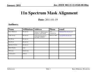
Spectrum Mask in IEEE802.11p. Authors:. Date: 2008-03-18. Abstract. We present the spectrum mask based on the FCC rule. WAVE system specification has mismatched spectrum masks. It means that PER(packet error rates) will be increased due to channel interference between adjacent channels.

E N D
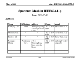
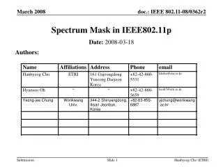
Spectrum Mask in IEEE802.11p Authors: Date: 2008-03-18 Hanbyeog Cho (ETRI)
Abstract • We present the spectrum mask based on the FCC rule. WAVE system specification has mismatched spectrum masks. It means that PER(packet error rates) will be increased due to channel interference between adjacent channels. • This presentation is a following work to the presentation by Vinuth Rai &John Kenny last San Fransisco meeting (17 July, 2008) • The main focus is on the spectrum mask related FCC rule and the spectrum mask should fulfill [55+10log(P)], -25dBm criteria • Then proposed spectrum mask will decrease the interference between adjacent channels Hanbyeog Cho (ETRI)
Contents Introduction Cross-Channel Interference Wave Regulation Spectrum Mask Hanbyeog Cho (ETRI)
Introduction • This presentation is relating to the presentation by Vinuth Rai &John Kenny last San Fransisco meeting(17 July, 2008) • 11-07-2133-00-000p-cross-channel-interference-test-results-a-report-from-the-vsc-a-project.ppt • Main focus : Interference adjacent channel • Spectrum Mask to fulfill [55+10log(P)], -25dBm criteria Hanbyeog Cho (ETRI)
Cross-Channel Interference • Effect of cross-channel interference • - Transmit power & channel allocation cross-channel interference • - Increasing PER • - Solution Need sharp spectrum mask • Ce = Co – Ci • - Ce : Total available channel • - Co : Original channel • - Ci : Channel interference Channel 1 Channel 2 Channel 3 Ce Interference Ci Ci Ci Ci Hanbyeog Cho (ETRI)
Toyota ITC test Result : Adjacent interference - Tx Channel : 172 - InterfererChannel: 174 Cross-Channel Interference : Example – Using WAVE • Toyota ITC test Result : • Non-adjacent interfer • - Tx Channel : 172 • - Control Channel: 178 • Cross-channel interference test results • - Adjacent channel interference • . Packet Error: [Tx-Rx distance] / [Int-Rx distance] > 10 if [PTx =PRx] • - Non-adjacent channel interference • . Less importance Hanbyeog Cho (ETRI)
Wave Regulation • Device classes and Tx power levels • Wave spectrum mask (D3.0) Hanbyeog Cho (ETRI)
IEEE 802.11p/D1.1 IEEE 802.11p Spectrum Mask (revision) • Spectrum Mask using 55+10log(P) , -25dBm Hanbyeog Cho (ETRI)
0 0 0 0 -10 -10 -10 -10 -20 -20 -20 -20 -30 -30 -30 -30 Power Attenuation(dBr) Power Attenuation(dBr) Power Attenuation(dBr) Power Attenuation(dBr) -40 -40 -40 -40 -50 -50 -50 -50 -60 -60 -60 -60 -70 -70 -70 -70 -15 -15 -15 -15 -10 -10 -10 -10 -5 -5 -5 -5 0 0 0 0 5 5 5 5 10 10 10 10 15 15 15 15 Offset Frequency(MHz) Offset Frequency(MHz) Offset Frequency(MHz) Offset Frequency(MHz) Spectrum Mask Class B Class A • IEEE 802.11p vs IEEE 802.11p/D1.1 Class C Class D Hanbyeog Cho (ETRI)
Conclusions We proposed basic spectrum masks to fulfill the FCC regulation rule. A present WAVE system specification has mismatched spectrum masks. It means that PER(packet error rates) will be increased due to channel interference between adjacent channels. This presentation is a following work to the presentation by Vinuth Rai &John Kenny last San Francisco meeting (17 July, 2008) . The proposed spectrum mask will decrease the interference between adjacent channels and the main focus is on the spectrum mask related FCC rule. Then the spectrum mask should be modified to fulfill [55+10log(P)], -25dBm criteria. Hanbyeog Cho (ETRI)
Insert the following text, table, and figures at the end of subclause I.2.3: For operation in the 5.85 - 5.925 GHz band in the USA, FCC CFR47 [B8], Section 90.377 and Section 95.1509, the transmitted spectrum shall be as follows and are summarized in Table I.7. Transmit Spectrum Mask: The DSRC transmitted spectrum mask is relative to the device class of operation. The power in the transmitted spectrum for all DSRC devices shall be –25 dBm or less within 100 kHz outside all channel and band edges. This will be accomplished by attenuating the transmitted signal 100 kHz outside the channel and band edges by 55 + 10log(P) dB, where P is the total transmitted power in watts. The transmitted spectral density of the transmitted signal for all devices shall fall within the spectral mask, as detailed in Table I.7. The measurements shall be made using a 100 kHz resolution bandwidth and a 30 kHz video bandwidth. The transmitted spectral mask for class A, B, C, and D devices are shown in Figures. I.3, I.4, I.5, and I.6. a) For Class A operation using 10 MHz channel spacing, the transmitted spectrum shall have a 0 dBr bandwidth not exceeding 9 MHz, and shall not exceed -10 dBr at 5 MHz frequency offset, -25 dBr at 5.5 MHz frequency offset, -33 dBr at 10 MHz frequency offset, -45 dBr at 15 MHz frequency offset and above. Figure I.3 shows the spectral mask for Class A operation. b) For Class B operation using 10 MHz channel spacing, the transmitted spectrum shall have a 0 dBr bandwidth not exceeding 9 MHz, and shall not exceed -16 dBr at 5 MHz frequency offset, -35 dBr at 5.5 MHz frequency offset, -43 dBr at 10 MHz frequency offset, -55 dBr at 15 MHz frequency offset and above. Figure I.4 shows the spectral mask for Class B operation c) For Class C operation using 10 MHz channel spacing, the transmitted spectrum shall have a 0 dBr bandwidth not exceeding 9 MHz, and shall not exceed -26 dBr at 5 MHz frequency offset, -45 dBr at 5.5 MHz frequency offset, -53 dBr at 10 MHz frequency offset, -63 dBr at 15 MHz frequency offset and above. Figure I.5 shows the spectral mask for Class C operation. d) For Class D operation using 10 MHz channel spacing, the transmitted spectrum shall have a 0 dBr bandwidth not exceeding 9 MHz, and shall not exceed -35 dBr at 5 MHz frequency offset, -53.8 dBr at 5.5 MHz frequency offset, -63.8 dBr at 10 MHz frequency offset, -73.8 dBr at 15 MHz frequency offset and above. Figure I.6 shows the spectral mask for Class D operation.
Table I.7— Class A thru Class D spectrum masks Hanbyeog Cho (ETRI)
0 0 0 0 -10 -10 -10 -10 -20 -20 -20 -20 -30 -30 -30 -30 Power Attenuation(dBr) Power Attenuation(dBr) Power Attenuation(dBr) Power Attenuation(dBr) -40 -40 -40 -40 -50 -50 -50 -50 -60 -60 -60 -60 -70 -70 -70 -70 -15 -15 -15 -15 -10 -10 -10 -10 -5 -5 -5 -5 0 0 0 0 5 5 5 5 10 10 10 10 15 15 15 15 Offset Frequency(MHz) Offset Frequency(MHz) Offset Frequency(MHz) Offset Frequency(MHz) Spectrum Mask Class B Class A • Figure I.4—Class B transmit spectrum mask • Figure I.3—Class A transmit spectrum mask Class C Class D • Figure I.6—Class D transmit spectrum mask • Figure I.5—Class C transmit spectrum mask Hanbyeog Cho (ETRI)
Motion (if technical and/or significant): • Move to accept the proposed text , table and figures from above slide 11,12 and 13 and instruct the TGp editor to incorporate the proposed changes. • Motion by: Hanbyeog Cho • Date: • Second: ______________________ Hanbyeog Cho (ETRI)