Download
1 / 102
1.02k likes | 1.22k Views
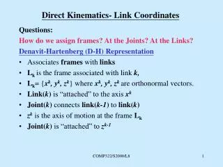
Direct Link Networks. Instructor: Rob Nash Readings: Chapter 2.1-2.4. End host. End host. Application. Application. Presentation. Presentation. Session. Session. Transport. Transport. Network. Network. Network. Network. Data link. Data link. Data link. Data link. Physical.

E N D
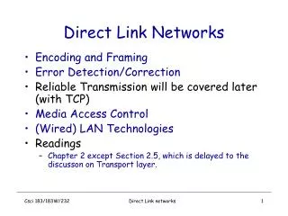
Direct Link Networks • Instructor: Rob Nash • Readings: Chapter 2.1-2.4
End host End host Application Application Presentation Presentation Session Session Transport Transport Network Network Network Network Data link Data link Data link Data link Physical Physical Physical Physical One or more nodes within the network Where We’ve Been…
And the “I” Internet Application Layer TCP UDP IP Network
A Word on Layers • “The protocol layer model makes a good slave but a poor master” • But, consider implementing functionality at the lowest level in the stack where you can offer this service completely* • *Effectively, reliably
Point-to-Point • The simplest network possible • Issues here will focus on the lowest protocols in our stack • A shared medium provides the link • Thus, media access control will be a recurring issue • Consider wireless & ethernet • All point to point concepts can be scaled up to internetworks simply by treating the gateway to two networks as the points/nodes in this example
Network Media • Optical Fiber • Twisted Pair • Category 5 • Air • The first step: 2 nodes connected by some medium
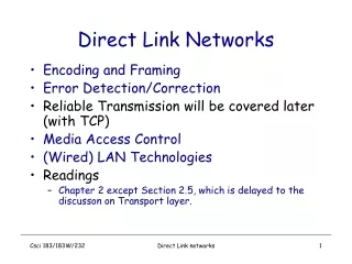
Issues With P-2-P Communication • How to encode bits on the wire? (physical layer) • How to frame bits into packages of meaningful data (framing) • How to deal with corruption during transmission • Error Detection & Error Correction • Checksums, CRCs, Multi-dimensional parity, etc. • Link reliability in spite of an unreliable physical world • MAC – a shared medium needs to be arbitrated in some meaningful way
Types of Networks So Far… • CSMA – • WiFi - • WiMAX – • FDDI (token ring) – • Note that for these shared-access networks, reliability may or may not be implemented at the link level, so we’ll turn our attention to point-to-point networks for now. • Scarce Network Resources Are?
A Typical Desktop Note: A node’s memory performance and it’s network performance are quite related! CPU NIC Cache RAM To Network I/O Bus
The NIC • What do Network Adapters do? • They are the interface, the middleman for the host and “the wild” • A host interface for use with the OS • A link interface for use with the physical link • Software on the host (device drivers called by OS) read from and write to the NIC’s CSR (status register) • How we tell the card “what to do”, and learn it’s current state • When data (a frame) arrives, we interrupt the host
DMA vs PIO (Programmed IO) • DMA allows the NIC to directly read and write memory without CPU involvement • Host gives the NIC an address, and the adapter reads from or writes to it • PIO relies on the CPU to move data • A “tight loop” that implies a copy • But, it could be infeasable for the device driver, OS, and application to go to memory multiple times for each word of data in a packet. • Esp if copying.
Parallels • There are many parallels between moving a message to and from memory and moving a message across a network • Memory speeds (and bus speeds) can provide a bottleneck • Key: We need to consider the memory bandwidth limitations (just like link level bandwidth limitations) as they affect our network performace • Implication: Network performing poorly? Not always the network’s fault! (could be a congested server) • Idea: try to coordinate OS & drivers & NIC to minimize buffer copies
The Memory/Processor Divide • While chips are still roughly following Moore’s law, memory is only increasing at about 7% a year (wrt speed, not density) • Implication: A network workstation will run at memory speeds, and not processor speeds • Critical Implications: How you manage your code (and more specifically, your memory transfers) can have a heavy impact on network performance
Encoding Data (Physical Layer) • We say that binary data is encoded in a signal, but how? • It’s a two-layer cake… • Modulation: varying the frequency, amplitude, phase, or any other physical characteristic of the signal in the medium for data encoding • Binary encoding: once we have some modulation system, this is the problem we’ll be focusing on • Hand-Waiving: as long as your sender can provide two (or more) distinguishable signals, we have our High/Low. • So, we’ll focus on the Binary Encoding problem
Cables, Leased Lines, Last Mile Links • Return to this with other slides
Fun Book Quote • “For example, two buildings belonging to the same organization but separated by a busy highway could communicate using lasers” (p79)
Encoding • NRZ • NRZI • Manchester • 4B/5B
Bits 0 0 1 0 1 1 1 1 0 1 0 0 0 0 1 0 NRZ NRZ – Nonreturn to zero • Great name! • Lets map the data value 1 onto the high signal, and the data value 0 onto the low signal.
Issues with NRZ • Long strings of 1s and 0s cause problems here • Clock recovery problems • Makes it difficult to know if we just observed one long 0, or actually three bits that were all 0 in a row • Baseline wander • Makes it difficult to calculate the threshold average to determine a high or low signal • What assumption/implication are we making?
Communication Requirements • The sender’s and receiver's clocks need to be precisely synchronized in order for the reciever to recover a frame accurately. • But a long time without a transition will affect the reciever’s ability to “tell time” – called clock drift • One approach is to try to artificially inflate the number of binary transitions by: • encoding additional bits • xoring data with a clock • Employing a wittier scheme than high == 1 and low == 0
Bits 0 0 1 0 1 1 1 1 0 1 0 0 0 0 1 0 NRZ Clock Manchester NRZI NRZI • The sender makes a transition from the current signal to encode a 1, and stays at the current signal to encode a 0. • This makes for lots of transitions if we see lots of 1s • But, what does this do for 0s?
Manchester Encoding • Aside: What’s a Manchester Machine? • ME: does an explicit job of merging the clock signal with the data by XORing the data with the clock • Lots of transitions here • Note that this implies only a 50% efficiency! • Another way to say this bit rate is half the baud rate • Baud rate being the rate at which the signal changes • Looking at the previous slide, note that the Manchester encoding is transitioning twice as fast as NRZ, NRZI • If the receiver can keep up with the doubled rate of the manchester encoding scheme, then it could keep up with NRZ,NRZI transmitting at twice their current rate (in our example)
4B/5B Encoding • Bit Stuffing • Encode 4 bits of data in 5 bits, with rules about the maximum number of 1s or 0s in a row • The 5-bit codes are selected such that no 5-bit code has more than one leading zero, and no more than two trailing 0s • 01100 • 001111 • 11000 • When sent back to back, this ensures no more than three consecutive 0s • What about ones? • What is a good solution here?
4B/5B Stuffing with NRZI • The bit stuffing takes care of strings of 0s, while NRZI takes care of strings of 1 • 80% Efficient
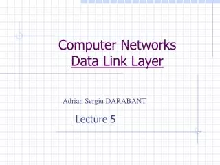
Framing • Break sequence of bits into a frame • Typically implemented by a network adaptor Bits Node A Adaptor Adaptor Node B Frame
Framing in the Data Link Layer • So we can transmit a bit or three – what to do with them? • Aggregating bits into larger structures – Framing • If we’re using packet switched networks, then we’re exchanging discreet packets • Contrast this to the IPC streaming abstraction we wish to provide • DL Goal: Trading frames of bits from one node’s memory to another across a link. • What about errors?
Frame error 8 16 16 8 Beginning Ending Header Body CRC sequence sequence Frame error Approaches • Sentinel-based • delineate frame with special pattern: 01111110 • e.g., HDLC, SDLC, PPP • problem: ending sequence appears in the payload • solution: bit stuffing • sender: insert 0 after five consecutive 1s • receiver: delete 0 that follows five consecutive 1s • Counter-based • include payload length in header • e.g., DDCMP • problem: count field corrupted (frame error) • solution: • Wait for the next beginning sequence • Catch when CRC fails
PPP – Byte-Oriented Protocols • Older protocols used this, still in use today • Collect a frame as a collection of bytes (chars) • BISYNC by IBM • DDCMP by DEC • PPP – recent and widely used, works in conjunction with LCP • These are “link layer” protocols • Notice the previous frame formats include a CRC or Checksum – what is that? • How does this affect link-level reliability?
Contrast with Bit-Level Protocols • Synchronous Data Link Control by IBM • Standardized by the ISO as HDLC • Note that bit stuffing (or character stuffing) implies a variable length frame (if the payload contains the END sentinel, we need to insert a DLE,but this grows the size of our frame!) • Thus, we’ll be considering networks with variable length frames • Contrast this to SONET
Bit Stuffing (and Unstuffing) • Used in bit-oriented protocols (HDLC) • High-Level Data Link Control (ISO version of SDLC from IBM) • Key: protect the sentinel by stuffing bits • 01111110 • Sender: anytime we see 5 consecutive 1s in the payload, stuff a zero in the stream • Receiver: if we see 5 consecutive ones, lookahead • If the next bit is a 0, it was stuffed (since the sentinel shouldn’t be here) so remove it. • If the next bit is a 1, lookahead (error or EOFrame) • If we see a 0, this is the EOFrame • If we see a 1, this is an error • See problem #5
SONET – Clock Based Framing • What if nodes all agreed on a frame length & a clock speed? • Less worry about clock wander & less complex without variable length frames • Sentinels do guard the boundaries of each frame, however. • SONET Frame quanta: 125microseconds • STS-1: 810 bytes long • STS-3: 810x3 = 2430 bytes long
SONET (cont) • Clock-based • each frame is 125us long • e.g., SONET: Synchronous Optical Network • STS-n (STS-1 = 51.84 Mbps) Interleaved every byte: keep 51Mbps for each STS-1
Error Detection • Basic Idea: Add redundant information to a frame that can be used to determine if errors have been introduced • And in some cases, we have enough information to correct the error • Do make the distinction, however, between correction and detection (and note that we’re concerned here with detection) • Parity bits • Checksums • Internet Checksum • CRCs
One-Dimensional Parity • Seven bits encode data, last bit encodes a “balance” bit • Even parity = choose last bit to have an even number of 1s • Odd parity = choose last bit to have an odd number of 1s • For Even parity, given the bit string “0101011X”, what should X be? • For Odd parity, given the bit string “1011001X” what should X be?
1 1 0 1 1 0 1011111 0110100 0001110 1011110 1101001 0101001 0 1111011 Multi-Dimensional Parity Parity bits Data Parity byte
Direct Link Networks • Instructor: Rob Nash • Readings: Ch2.4-2.5 (2.6-2.7) • Today: • CRC • Stop-and-wait • Sliding window • Homework Problems • Announcements: • Schedule to be updated by thursday (off-by-one) • New assignment out today • Our first exam is weeks away! (May 5th) • Exam review next thursday
Internet Checksum • View message as a sequence of 16-bit integers; • Convert each 16-bit integer into a ones-complement arithmetic • Sum up each integer • Increment the result upon a carry
One’s Compliment • -5 is ? • -2 is? • Negate the “positive” version • Add one on a carry • Is zero positive or negative?
Code Example u_short cksum(u_short *buf, int count) { register u_long sum = 0; while (count--) { sum += *buf++; if (sum & 0xFFFF0000) { // carry occurred, so wrap around sum &= 0xFFFF; sum++; } } return ~(sum & 0xFFFF); }
Cyclic Redundancy Check • Based on polynomials and Finite Fields • Math may be daunting at first, but the practice isn’t difficult • Can be done quickly using shift registers and XOR gates • First, some background on polynomial arithmetic
Algorithmic Overview • We want to divide our message M(x) by a well known key and produce the remainder • The choice of the key determines the errors it will protect against • Once we have the remainder, we can subtract this from our original message A, which guarantees A % key == 0 • That is, our C(X) evenly divides our new message P(x) • P(x) is M(x) plus the k redundant bits for the CRC • If the receiver sees that P(x) Mod C(x) == 0, we can discard the CRC bits and obtain the original M(x) • Plus, be certain we avoided a large class of bit-level errors
Polynomial Arithmetic • B(x) / C(x) is allowable, provided degree(B(x)>=C(x)) • If == to, then of course, only one division is performed • The remainder of B(x)/C(x) is obtained by polynomial subtraction • To find the B(x) mod C(x), “subtract” C(x) from B(x) • To subtract, simply XOR the two bit patterns
An Example • Lets do problem 18 in the text • M(x) = 1100 1001 • What poly does this represent? • C(x) = x^3 + 1 • What is this in binary representation?
The Remainder • Shift (multiply) our M(x) by k, where k is given by the generator polynomial (in this case, k = 3) • This is T(x) • Perform the “long division” using the poly subtraction technique • (note: not really long division; long poly subtraction?) • Poly subtract the remainder from your (zero-extended) message, T(x) and send this message • Note that the message is really M(x) & CRC bits
Picking the Appropriate C(x) • You pick this amongst a set of known polynomials that are designed to catch specific types of bit-level errors • We can prove that the following types of errors can be detected by a C(x) with the stated properties: • All single-bit errors, as long as x^kand x^0are nonzero • All double-bit errors, as long as C(x) has a factor with 3 or more terms • Any odd number of errors, as long as C(x) contains x + 1 • Any burst error for which burstLen < k • However, most burst errors larger than k can also be detected • Summary: the stronger the mathematical technique, the stronger the detection and/or fewer redundand bits • See p101. for a list of common CRCs
Reliability • The ability to send and receive successfully • The application developer’s perspective might be: • No lost packets • No out of order packets • No duplicate packets • No corrupt packets (we just dealt with this : LL strategies) • Usually, two strategies are used: ACKS and timeouts
ACKnowledgements • A small control frame belonging to a protocol that is sent as a receipt of data transmission • Control here: all header and no payload • You could also attach an ACK to a payload packet (piggyback) • If the sender doesn’t see an ACK in a “reasonable” amount of time, what has happened?
Timeouts • “The action of waiting a reasonable amount of time.” • When we’ve run out of wait time! • The combination of ACK & timeout mechanisms: ARQ • Automatic Repeat Request
Acknowledgements & Timeouts Receiver can’t distinguish if the 1st and 2nd frames are identical CSS 432
Simple ARQ : Stop-and-Wait • Transmit a frame; stop, and wait. • Advantages? Disadvantages? • See p.103