PIC18F
PIC18F. Architecture. PIC18F Architecture. PIC18F. Harvard Architecture Program Memory : Flash 4KB to 128KB Data Memory : SRAM 256 to 3968 bytes Data EEPROM: 128 bytes to 1KB if any 18 to 100 Pins I/O Pins : 16 to 70 25 MHz to 48 MHz.

PIC18F
E N D
Presentation Transcript
PIC18F Architecture
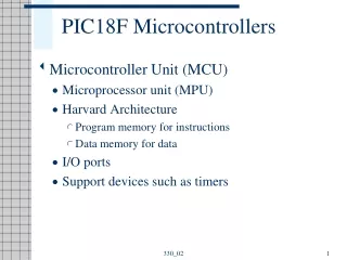
PIC18F • Harvard Architecture • ProgramMemory: Flash 4KB to 128KB • Data Memory: SRAM 256 to 3968 bytes • Data EEPROM: 128 bytes to 1KB ifany • 18 to 100 Pins • I/O Pins: 16 to 70 • 25 MHz to 48 MHz
I/O Ports • Five I/O ports • PORT A through PORT E • Most I/O pins are multiplexed • Generally have eight I/O pins with a few exceptions • Addresses already assigned to these ports in the design stage • Each port is identified by its assigned SFR
MCU SupportDevices • Timers • CCP Modules: Capture, Compare and PWM • Serial Communications • MSSP: Master Synchronous Serial Port • Addressable USART • A/D converter • PSP: Parallel Slave Port • Data EEPROM
PIC18F SpecialFeatures • Sleep Mode • WDT: Watchdog Timer • Code Protection • In-Circuit Serial Programming • In-Circuit Debugger
PIC18F Instructions and Assembly Language • Has 77 instructions • Earlier PIC family of microcontrollers have either 33 or 35 instructions. Upward Compatible. • In PIC18F instruction set, all instructions are 16-bit word length except four instructions that are 32-bit length
Instruction Description • Copy (Move) 8-bit number (Literal) into W register • Mnemonics: MOVLW 8-bit • Binary format: 0000 1110 XXXX XXXX (any 8-bit number) • Copy (Move) contents of W register into PORTC (File) • Mnemonics: MOVWF PORTC, a • (‘a’ indicates that PORTC is in the Access Bank) • Binary format: 0110 1110 1000 0010 (82H is PORTC address)
Illustrative Program: Displaying a Byte at an I/O Port • Problem statement: • Write instructions to light up alternate LEDs at PORTC • Hardware: • PORTC • bidirectional (input or output) port; should be setup as output port for display • Logic 1 will turn on an LED
Program • Logic 0 to TRISC sets up PORTC as an output port • Byte 55H turns on alternate LEDs • MOVLW 00 ;Load W register with 0 • MOVWF TRISC,0 ;Set up PORTC as output • MOVLW 0x55 ;Byte 55H to turn on LEDS • MOVWF PORTC,0 ;Turn on LEDs • SLEEP ;Power down
EmbeddedSystem Microcontroller-based Time and Temperature System