Download

1 / 32
320 likes | 616 Views
Op-Amps. …and why they are useful to us. Greg Henderson Abdul Jaroudi Nishanth Mehanathan. Outline of Presentation. What is an Op-Amp? Characteristics of Ideal and Real Op-Amps Common Op-Amp Circuits Applications of Op-Amps References. What is an Op-Amp?.

E N D
Op-Amps …and why they are useful to us Greg Henderson Abdul Jaroudi NishanthMehanathan
Outline of Presentation • What is an Op-Amp? • Characteristics of Ideal and Real Op-Amps • Common Op-Amp Circuits • Applications of Op-Amps • References
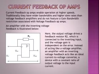
What is an Op-Amp? • An Operational Amplifier (known as an “Op-Amp”) is a device that is used to amplify a signal using an external power source • Op-Amps are generally composed of: • Transistors, Resistors, Capacitors = + +
Brief History • First patent for Vacuum Tube Op-Amp (1946) • First Commercial Op-Amp available (1953) • First discrete IC Op-Amps (1961) • First commercially successful Monolithic Op-Amps (1965)
History Continued… • Leading to the advent of the modern IC which is still used even today (1967 – present) Fairchild μA741 Electrical Schematic of μA741
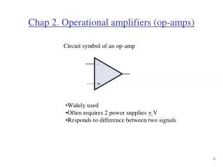
Op-Amps and their Math A traditional Op-Amp: V+ V- Vout Vs+ Vs- : non-inverting input : inverting input : output : positive power supply : negative power supply Vout = K (V+ - V-) • The difference between the two inputs voltages (V+ and V-) multiplied by the gain (K, “amplification factor”) of the Op-Amp gives you the output voltage • The output voltage can only be as high as the difference between the power supply (Vs+ / Vs-)and ground (0 Volts)
Saturation Saturation is caused by increasing/decreasing the input voltage to cause the output voltage to equal the power supply’s voltage* The slope is normally much steeper than it is shown here. Potentially just a few milli-volts (mV) of change in the difference between V+ and V- could cause the op-amp to reach the saturation level Vout VS+ Slope = K (“gain of Op-Amp”) Vin * Note that saturation level of traditional Op-Amp is 80% of supply voltage with exception of CMOS op-amp which has a saturation at the power supply’s voltage VS- Saturation Points
Outline of Presentation • What is an Op-Amp? • Characteristics of Ideal and Real Op-Amps • Common Op-Amp Circuits • Applications of Op-Amps • References
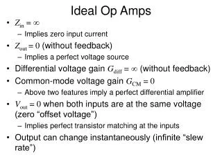
An Ideal Op-Amp • Infinite voltage gain • Infinite input impedance • Zero output impedance • Infinite bandwidth • Zero input offset voltage (i.e., exactly zero out if zero in). http://hyperphysics.phy-astr.gsu.edu/hbase/electronic/opamp.html#c4
Ideal versus Real Op-Amps Ideal Real http://hyperphysics.phy-astr.gsu.edu/hbase/electronic/opamp.html#c4
Outline of Presentation • What is an Op-Amp? • Characteristics of Ideal and Real Op-Amps • Common Op-Amp Circuits • Applications of Op-Amps • References
Basics of an Op-Amp Circuit • An op-amp amplifies the difference of the inputs V+ and V- (known as the differential input voltage) • This is the equation for an open loop gain amplifier: Vout=K(V+-V-) • Kis typically very large – at around 10,000 or more for IC Op-Amps • This equation is the basis for all the types of amps we will be discussing
Open Loop vs Closed Loop • A closed loop op-amp has feedback from the output to the input, an open loop op-amp does not Open Loop Closed Loop
Non-Inverting Op-Amp • Amplifies the input voltage by a constant • Closed loop op-amp • Voltage input connected to non-inverting input • Voltage output connected to inverting input through a feedback resistor • Inverting input is also connected to ground • Non-inverting input is only determined by voltage output
Non-Inverting Op-Amp Vout=K(V+-V-) R1/(R1+R2) Voltage Divider V-=Vout (R1/(R1+R2) ) Vout=[Vin-Vout (R1/(R1+R2))] K Vout=Vin/[(1/K)+ (R1/(R1+R2))] As discussed previously assuming, K is very large, we have: Vout=Vin/(R1/(R1+R2)) Vout=Vin (1+(R2/R1))
Inverting Op-Amp • Amplifies and inverts the input voltage • Closed loop op-amp • Non-inverting input is determined by both voltage input and output • The polarity of the output voltage is opposite to that of the input voltage • Voltage input is connected to inverting input • Voltage output is connected to inverting input through a feedback resistor • Non-inverting input is grounded
Inverting Op-Amp Vout=K(V+-V-) V-=Vout(Rin/(Rin+Rf))+Vin(Rf/(Rin+Rf)) V-=(VoutRin+VinRf)/(Rin+Rf) Vout=K(0-V-) Vout=-VinRf/[(Rin+Rf)/K+(Rin)] Vout=-VinRf/Rin
Integrating Op-Amp • Integrates the inverted input signal over time • Closed loop op-amp • Voltage output is connected to inverting input through a capacitor • The resistor and capacitor form an RC circuit • Magnitude of the output is determined by length of time voltage is present at input • The longer the input voltage is present, the greater the output
Integrating Op-Amp • When the circuit is first connected the capacitor acts as a short. Gain is less than 1, Vout is 0 • As time progresses, and the capacitor charges, it’s effective resistance increases. Now Vout is increasing as well • When the capacitor is fully charged it acts as an open circuit with infinite resistance. Now Voutgoes into saturation (~80% power supply voltage) • The rate of voltage output increase depends on the RC time constant Vout=-VinRC/Rin
Integrating Op-Amp • An integrating op-amp circuit can create a sawtooth signal if a square wave is applied at Vin
Differential Amplifier Voltage relations • The purpose of the differential amplifier is to produce an output proportional to the difference of the input voltages • V+is given by the voltage divider equation
Differential Amplifier continued Output voltage Vout as we see is the difference of voltage V1 & V2 multiplied by the resistance R4 & R3 which scales the difference
Summing Amplifier Output voltage The summing amplifier does exactly as the name suggests by adding up the voltages given to it and producing an output voltage which is the sum of the input voltages scaled by the feedback resistance and input resistance
Summing Amplifier continued The graph shown above is a plot of output voltage Voutvs input voltage Vin 3
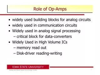
Outline of Presentation • What is an Op-Amp? • Characteristics of Ideal and Real Op-Amps • Common Op-Amp Circuits • Applications of Op-Amps • References
Applications - Filters • Types: • Low pass filter • High pass filter • Band pass filter • Cascading (2 or more filters connected together) Low pass filter C R2 Low pass filter transfer function R1 + Vcc - + V0 __ + - Vcc + Low pass filter Cutoff frequency -
Applications - Strain Gauge Use a Wheatstone bridge to determine the strain of an element by measuring the change in resistance of a strain gauge (No strain) Balanced Bridge R #1 = R #2 (Strain) Unbalanced Bridge R #1 ≠ R #2
Applications - Strain Gauge Op amp used to amplify output from strain gauge Half-Bridge Arrangement R + ΔR Rf R Vref + Vcc + - + V0 __ + - - Vcc R R - ΔR Rf Using KCL at the inverting and non-inverting terminals of the op amp we find that ε ~ Vo = 2ΔR(Rf/R2)
PID Controller – System Block Diagram P I VOUT VSET VERROR Output Process D VSENSOR Sensor • Goal is to have VSET = VOUT • Remember that VERROR = VSET – VSENSOR • Output Process uses VERROR from the PID controller to adjust Vout such that it is ~VSET
ApplicationsPID Controller – System Circuit Diagram Signal conditioning allows you to introduce a time delay which could account for things like inertia System to control -VSENSOR Source: http://www.ecircuitcenter.com/Circuits/op_pid/op_pid.htm
ApplicationsPID Controller – PID Controller Circuit Diagram VERROR PID VERROR
References: • 1. Student lecture Fall 2009, Andrew Gibson, Konstantin Froelich, Benjamin Haefner, RoshanKalghatgi. http://www.me.gatech.edu/mechatronics_course/ • 2. PID controller http://en.wikipedia.org/wiki/PID_controller • 3. Operation amplifier applications http://en.wikipedia.org/wiki/Operational_amplifier_applications • 4. http://www.wisc-online.com/ • 5. http://hyperphysics.phy astr.gsu.edu/hbase/electronic/opamp.html#c4