Download
1 / 20
200 likes | 218 Views
Explore input/output mechanisms and interrupt handling in computer systems, using CdM-8 architecture as a case study. Learn about polling vs. interrupts, IRQ signals, vector instructions, and more.

E N D
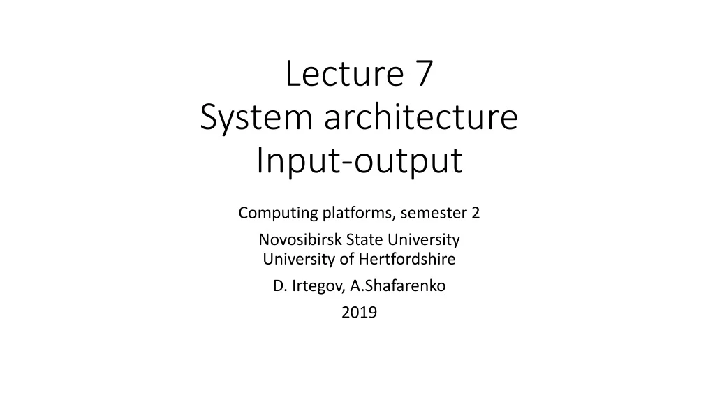
Lecture 7 System architectureInput-output Computing platforms, semester 2 Novosibirsk State UniversityUniversity of Hertfordshire D. Irtegov, A.Shafarenko 2019
CdM-8 as a chip Unmarked outputs on the top: register monitors IRQ, vector and IAck we will discuss later In and out buses are memory bus
I/O as a memory cell • Sequential logical device is • a set of registers • some combinatory logic • If we make some registers available to CPU, we can • Read [parts of] state of the device • It is up to device designers to make this part of the state usable • Change state of the device (issue commands and transfer data)
Reading data from the keyboard • Uppermost (7th) bit of data latch is reset to 0 on key press • And to 1 on data read • Thus, CPU can poll (repeatedly read) the data until bit 7 is 0 • While polling, CPU cannot do anything else • Also, polling leads to high CPU load and power consumption • If CPU does something else (timed polling), it cannot react to keyboard immediately • In multithreaded programming, polling is considered harmful • But on low level I/O you sometimes have no other choice
Interrupts (alternative to polling) • Interrupts are hardware service that allows • I/O devices to signal events • CPU to handle (process) them • Require changes to CPU internal architecture • CPU must poll IRQ signal on every fetch cycle • If the signal is present, instead of fetching next instruction CPU starts interrupt handling sequence • To handle interrupt, CPU saves parts of its state (PC and PS registers) and calls a handler (interrupt service routine, ISR)
Changes to CdM-8 CPU Interrupt Master (IM) , which senses interrupt requests, decides if the interrupt must be granted and fetches the interrupt vector from the device Interruptable Sequencer latching Virtual Interrupt Instruction (VII) instead of a normal Fetch based on the PC. Extension of the Secondary Decoder to accommodate the execution of the VII, Extension of the Instruction Set with the rti instruction (return from interrupt): the last instruction that an ISR must execute. Interrupt Arbiter handles the situation when several devices request interrupts at overlapping periods
Why handle interrupts only on Fetch stage? If we handle interrupts only between ISA instructions, we can save registers needed for ISR programmatically (and not save ones not needed) If we handle interrupts inside of the instructions, we must save all state of the CPU, including registers which are not available programmatically (IR, RR, RX, sequencer state) In industrially used CPU, that would break compatibility between CPUs with same ISA but different RTL architecture (e.q. AMD and Intel)
Peripherals vector IM … int IRQ InterruptArbiter InterruptArbiter vec-adr IAck v2 v1 IRQ IRQ IAck IAck device i/f device i/f hold fetch int enabled DP triggers phase1 Secondary Decoder Sequencer … int … latch phase5 op-code fetch fetchlogic taken CVZN Primary Decoder PS branch logic PC=PC+1 read latch shared with DP cond instr instr PC Memory IR DP selectors addr shared with DP int
Interrupts from software point of view Every interrupt-capable device has unique number on range 0 to 7 Every possible value of device numbers selects a byte pair, called interrupt vector By default, interrupt vectors are mapped to upper 16 bytes of memory In Manchester architecture, these are same bytes as used for memory mapped I/O, so you cannot use all 7 interrupts and all 16 register addresses In Harvard architecture, I/O is mapped to data memory, and vectors to program memory
But what happens when interrupt occurs? • Device sets IRQ request on CPU input line • When CPU finishes every instruction, it polls IRQ request line • If interrupts are enabled (we will discuss this later), it retrieves device number • Then, instead of instruction at mem[PC], VII (ioi) instruction is executed • In some sence, ioi is “normal” instruction: it has an opcode, it can be inserted in a machine code and executed like any other command • This is called “software interrupt” • But during interrupt, no ioi instruction is present at mem[PC] • But CPU behaves like it fetched this instruction
Ioi instruction Phase 1 decrement SP for stack push Phase 2 store PC on stack; decrement SP for stack push Phase 3 store PS on stack Phase 4 fetch new PC value from vector’s first cell (0xf0 + 2R) Phase 5 fetch new PS value from vector’s second cell (0xf1 + 2R) It is similar to jsr, but two registers are saved (PC and PS) You need to use rti instruction to return from ioi routine And call target depends on hardware (device number R) So you can write specific handler routine for every device
What you can do in interrupt handler? Typically, interrupt signals that device has some data for you So you must retrieve the data Some devices require further instructions, what to do next For example, when you read data from the disk, you must tell the disk what sector to read or write next (or not tell anything and disk will be idle) Then you must set some flags so main program will know the data are ready Then you must return to main program (execute an rti instruction) Or you can do something else (we will discuss it in Operating Systems course)
Why interrupts are bad? They are asynchronous They can occur in any moment of program execution It is very easy to write a handler that can break a main program (damage its data) And it is very hard to catch this condition by testing So, there is a mechanism to disable interrupts (a flag in PS register) Interrupt handling is a simplest (and historically first) form of parallel programming, and parallel programming has many pitfalls And most of these pitfalls are hard to avoid There will be courses on concurrency and parallel programming further in our curriculum
Why interrupts are good? You can handle several event sources at same time You do not need to rewrite your program to add another event source You can do something useful when waiting for an event Operating systems use interrupts to implement multithreading and multitasking
Terminal device Has a full ASCII keyboard and ASCII display I/O port is shared: in is kbd, out is screen Kbd sends interrupt when key is pressed
Terminal device driver ISR reads the char from keyboard And inserts it into a ring buffer Main program can read the data from the buffer, when it is not busy with other tasks Output data are put to the screen immediately Code is in the tome.pdf