Download
1 / 21
230 likes | 376 Views
Physics of ultrathin photovoltaics. Ultrathin photovoltaics. Rare materials. Indium in CIGS solar cell. Tellurium in CdTe solar cell. To reduce material consumption. Ultrathin photovoltaics. Advantages Low cost Rapid process Material conservation. Submicron absorber thickness.

E N D
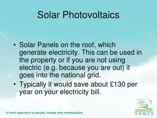
Ultrathin photovoltaics Rare materials Indium in CIGS solar cell Tellurium in CdTe solar cell To reduce material consumption Ultrathin photovoltaics Advantages Low cost Rapid process Material conservation Submicron absorber thickness
Optical absorption Light absorption Thin absorption layer Optical loss by insufficient light absorption Light trapping Texturing Photonic crystal Nanowire
Appl. Phys. Lett. 89, 163518 (2006) Electrical characteristics Depletion width vs. Film thickness Ldep > l : Complete depletion Film behaves as a dielectric Bulk recombination is insignificant Important features Screening by electrodes Leakage currents Dielectric breakdown
Electrical characteristics 1. Electrode screening Statistical fluctuation of random potential In case of randomly distributed electric charge, For typical gaussian distribution And potential distribution For n~1014-1016cm-3 For case of grain boundary charge, Much less N~10 (assumption)
Physical Review B 69, 045325 (2004) Electrical characteristics 1. Electrode screening Screening by electrodes Screening length Physical meaning : φ fluctuation is balanced by potential drop across the resistive electrode Minimum Screening length In case of , microdiodes interact strongly When two diodes are in parrellel, Low VOC diode under forward bias u and Supplied by the diodes in the surrounding region within L
Physical Review B 69, 045325 (2004) Electrical characteristics 1. Electrode screening Particle size Very small particle size : Large N → Insignificant potential fluctuation Very large particle size : Columnar grain diameter exceeds l → Boundary potential vanishing towards the electrodes Series resistance Diodes in parallel : Most current through weak diode → Voltage drop Series resistance : Equil out the differences in the diodes (Low value)
Electrical characteristics 2. Leakage currents Defects & Shunting pathways Electron tunneling between defects ↓ Hopping conduction through defect chain Shunt resistance Currents through diode and resistor add up ↓ Reduce VOC & FF
Electrical characteristics 2. Leakage currents Probability of finding an N-defect pathway from ref. 9 - Mesoscopic Phenomena in Solids Hopping resistance Probabilistic distribution of pathway resistances
Electrical characteristics 2. Leakage currents Geometrical consideration When radial distribution does not suppress tunneling ↓ l/N a r Characteristic distance
Electrical characteristics 2. Leakage currents Probability of finding an N-defect pathway Effective shunt resistance To find at least one of effective leakage Critical thickness Lower bound estimate : Non-ohmicity or correlated defect distribution increase
Electrical characteristics 3. Dielectric breakdown Capacitive energy consideration Driving force : Decrease in capacitive energy by shunt formation and induced voltage decrease Stored energy By shunt resistance Defect formation W~10 GeV for typical Defect generation energy w~10 eV In reality, just several defects can form a shunt pathway
Electrical characteristics 3. Dielectric breakdown Low illumination Stored energy is a maximum at low light Shunting & degradation
Summary Efficiency loss mechanisms in ultra-thin solar cells Screening by electrodes Leakage currents Dielectric breakdown In standard device, above effects cannot be suppressed by technology improvement Potential remedy : Properly designed interfacial layers → Increasing defect chan resistance → Mitigating leakage and breakdown vulerability
Mater. Res. Soc. Symp. Proc. 668 (2001), p. H6.4. Case #1 Ultra-thin CdTe device Device characteristic Reduced photon collection in red ↓ JSC loss is expected In reality, 12% eff. in 3μm device ↓ 5% eff. In 0.5μm device VOC drop is more responsible to efficiency loss
Solar Energy Materials & Solar Cells 90 (2006) 2263-2271 Case #1 Ultra-thin CdTe device Device reoptimization Reoptimized processes : CdCl2 treatment Back contact diffusion Chloride processing produces intermixed alloy layer of CdSTe more quickley Shorter CdCl2 processing prevents overgrowth of alloy layer Shorter back contact diffusion prevents Cu out-diffusion into the junction region
J. Appl. Phys. 98, 103703 (2005) Case #2 Ultra-thin CIGS device Optical absorption At 0.5μm thickness, Efficiency is not sensitive to Back contact reflectivity (RB) There is no significant optical loss when t>0.5μm Experimently, JSC losses in thin cells are higher than calculation
J. Appl. Phys. 98, 103703 (2005) Case #2 Ultra-thin CIGS device Back contact 1. Depleted cells (d<0.3μm) JSC is nearly independent 2. Medium thickness cells (d~0.4-1.0μm) Larger back barrier → Larger back-contact depletion region → Attracts electrons and Increases JSC losses 3. Thick cells Independent of back-contact barrier height
J. Appl. Phys. 98, 103703 (2005) Case #2 Ultra-thin CIGS device Bandgap grading VOC increases in graded cell (Reduced bulk recombination) Grading in thick cells, Improved current collection about 1-2 mA/cm2 In thin cells, More significant current losses by bandgap increase Almost no collection benefit in depleted cells
Nature 449, 885-889 (2007) Case #3 Coaxial Si NW solar cell Breakdown voltage p-n diode : negative temperature dependence → Zener breakdown mechanism p-i-n diode : little temperature dependence → Tunneling and avalanche breakdown mechanism p-i-n diodes have higher breakdown voltage Tunneling or leakage current is less significant in p-i-n diodes
In our concept We have to overcome following issues : Optical light-trapping Ohmic contact Back contact barrier – Not required in fully depleted cells p-i-n structure can be required TCO(AZO) CIGS thin layer SiOx thin layer CdS thin layer Si nanowire Si SUBSTRATE