Download
1 / 10
100 likes | 284 Views
Learn how ammeters measure current, voltmeters measure voltage, and ohmmeters measure resistance in circuits. Design examples for ammeters and voltmeters included. Understand their functions and how to ensure accurate readings. Summary of key concepts in electrical measurements.

E N D
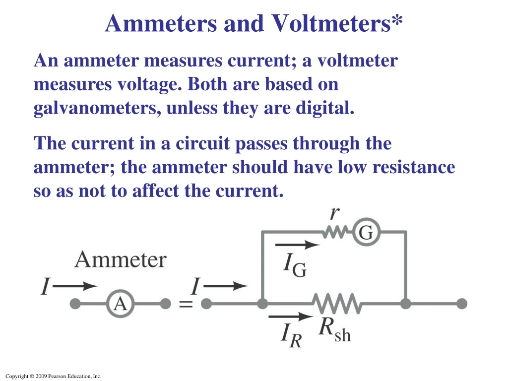
Ammeters and Voltmeters* An ammeter measures current; a voltmeter measures voltage. Both are based on galvanometers, unless they are digital. The current in a circuit passes through the ammeter; the ammeter should have low resistance so as not to affect the current.
Example : Ammeter design. Design an ammeter to read 1.0 A at full scale using a galvanometer with a full-scale sensitivity of 50 μA and a resistance r = 30 Ω. Check if the scale is linear.
A voltmeter should not affect the voltage across the circuit element it is measuring; therefore its resistance should be very large.
Example : Voltmeter design. Using a galvanometer with internal resistance 30 Ω and full-scale current sensitivity of 50 μA, design a voltmeter that reads from 0 to 15 V. Is the scale linear?
An ohmmeter measures resistance; it requires a battery to provide a current.
Summary: An ammeter must be in series with the current it is to measure; a voltmeter must be in parallel with the voltage it is to measure.
Example: Voltage reading vs. true voltage. Suppose you are testing an electronic circuit which has two resistors, R1 and R2, each 15 kΩ, connected in series as shown in part (a) of the figure. The battery maintains 8.0 V across them and has negligible internal resistance. A voltmeter whose sensitivity is 10,000 Ω/V is put on the 5.0-V scale. What voltage does the meter read when connected across R1, part (b) of the figure, and what error is caused by the finite resistance of the meter?
Summary of Chapter • A source of emf transforms energy from some other form to electrical energy. • A battery is a source of emf in parallel with an internal resistance. • Resistors in series:
Resistors in parallel: • Kirchhoff’s rules: • Sum of currents entering a junction equals sum of currents leaving it. • Total potential difference around closed loop is zero.
RC circuit has a characteristic time constant: • To avoid shocks, don’t allow your body to become part of a complete circuit. • Ammeter: measures current. • Voltmeter: measures voltage.