Advanced Machine-Detector Interface for High Luminosity SC-TF Collider at Budker Institute
This presentation discusses key boundary conditions for achieving high luminosity in the SCTF collider, focusing on the essential machine-detector interface parameters. The proposed solution involves the use of a compensating solenoid to counteract betatron coupling effects from a primary 1.5 T solenoidal field. Emphasis is placed on minimizing vertical emittance and ensuring optimal beam dynamics through carefully positioned defocusing lenses and solenoid configurations. The workshop outlines the critical geometry and magnetic field requirements to enhance collision effectiveness.

Advanced Machine-Detector Interface for High Luminosity SC-TF Collider at Budker Institute
E N D
Presentation Transcript
Machine-Detector Interface S. Sinyatkin Budker Institute of Nuclear Physics 26September 2019 Joint Workshop on Future charm-tau Factory
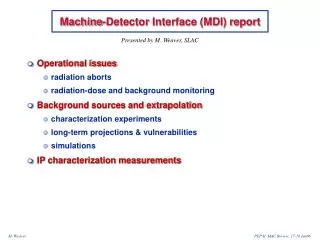
Boundary conditions I • To obtain high luminosity of the SCTF collider, small transverse beam size at the IP is required. • Detector creates 1.5 T solenoidal field of 0.6m length with minimum material (accelerator components) in this area. • On the reference orbit solenoid field produces betatron coupling, dispersion and finally blows up the vertical emittance. • To suppress the betatroncoupling produced by main detector solenoid field, a compensating solenoid is required.
Boundary conditions II • For better beam dynamics the distance between the IP and the first defocusing lens (L*) should be as short as possible. • The full crossing angle of 60 mrad is required for the Crab-Waist scheme. The horizontal field and the betatron coupling appear when the solenoids axis do not coincide with the beam trajectory. • A cross-talk between the detector field and the FF quadrupoles should be avoided (otherwise it produces unwanted field components). The longitudinal field decay area for large aperture solenoids is large and complicates the betatron coupling compensation scheme.
SCTFParameters *) Two superconducting wigglers with 3.5 T and 1.5 m long to reduce damping time from ms to ms A. Bogomyagkov
Interaction Region (IR) • On beam trajectory detector creates 1.5 T solenoidal field of 0.6 m length, needs to be compensated. • Vertical emittance budget is 30 pm for the solenoid fields. • Full crossing angle is 60 mrad. • Accelerator equipment should be inside the 0.175 rad cone. • A space between Y-chamber and the cryostat is needed to accommodate BPM, flange, bellows, HOM absorber(?), luminometer (?!), etc. • Collimation system (?!) • First (defocusing) quad QD0 is at L*= 0.9 m from the IP.
Detector geometry IR area: BPMs, flanges, bellows, compensating solenoids, screening solenoids, FF quadrupole lenses, steering magnets. Additional screening area.
Baseline IR layout Be- chamber 0.175 rad Y- chamber 0.54m QD0 QF1 Compensating Solenoid 0.15 m Screening Solenoid IP 0.65m FF Quads 0.85m 0.9m 0.74m
Machine-detector interface Compensating Solenoid Screening Solenoid Y- chamber Be- chamber BPM FF Quads
Vacuum chamber, Super KEKB example Vacuum pipe cooling lines Vacuum pipe flange Be- chamber Y- chamber Flanges Bellows
FF lenses One of the most essential element of the Super CT FF is a dual aperture superconducting quadrupole to squeeze the beams at the IP with the following parameters: IP QD0 QF1 IP 3.3 m IP Cryostat with FF magnets Beam trajectories in FF Cryostat with FF magnets Artist view of the FF arrangement
FF lenses • Main requirements: • Compactness. • No transverse interference between elements. • High quality magnetic field in the aperture.
Vacuum chamber: warm to cold (A. Krasnov) https://indico.cern.ch/event/803859/contributions/3344818/attachments/1807687/2950964/BINP_MDI_Mar_2019.pptx
Compensating scheme of solenoid fields Cylindrical Compensating Solenoid QF1 QD0 Bs_main Screening Solenoid Bs_comp FF Quads
Cylindrical solenoids Y S IP X
Distribution of magnetic field components along reference trajectory Cylindrical solenoid for a both beams Magnetic field at QD0 entrance (0.9 m): Bx = 0.3 T Bs = 0.9 T G_skew= 0 T/m Rharmonic = 10 mm An < 10-4 , n≠1 Bn < 10-4 Cylindrical Compensating Solenoid Screening Solenoid FF Quads
Vertical emittance calculation for baseline I2 = 0.832m-1βy* = 0.5 mm
Distribution of magnetic field components along reference trajectory Cylindrical solenoid for a both beams IP IP
How to decrease vertical emittance & fringe fields • Decreasing the length of the main solenoid • Increasing the length of compensating solenoid • Increasing βy_IP • Redistributing current in compensating solenoid • Reducing the main solenoid field: • Introducing elliptical shape of compensating solenoids and additional correctors εy~I5,y ~ Bx5 ~ Bs5
Compensating solenoid Screening solenoids -Elliptical for a both beams Compensating solenoids Dipole & Skew quad corrections
Compensating solenoid -Cylindrical for a both beams -Elliptical for a both beams Screening solenoids Compensating solenoids Dipole & Skew quad corrections
Compensating solenoid -Elliptical for a both beams (3) Dipole & Skew quad corrections At s = 0.62 m At s = 0.84 m
Compensating solenoid -Elliptical for a both beams (3) Dipole & Skew quad corrections At s = 0.62 m -I1 +I1 -I1 +I1 +I2 -I2 -I2 +I2 +I1 -I1 +I1 -I1 I1 = kb*Bx – kg*Gskew I2 = 2*kb*Bx Rharm = 10 mm
Compensating solenoid -Elliptical for a both beams (Example) Dipole & Skew quad corrections At s = 0.62 m Bx = 0, Gskew ≠ 0 I1 =400 A I2 = 0 A Bx ≠ 0, Gskew = 0 I1 =-400 A I2 = 800 A I1 = kb*Bx – kg*Gskew I2 = 2*kb*Bx Rharm = 10 mm, Bn ≈ 0
Distribution of magnetic field components along reference trajectory Elliptical solenoid for a both beams
Distribution of magnetic field components along reference trajectory Elleptical solenoid for a both beams & correctors IP IP
Summary • The basic layout provides acceptable vertical emittance blow up. • Solenoidal magnetic fields in a quadrupole lens require additional correction. • New MDI design completely eliminates emittance blow up due to the horizontal field at the orbit and local betatron coupling (y<0.5 pm*rad). • The new scheme provides small magnetic fields in the quadrupoles area and additional room for other devices. • The new scheme has all accelerator components in175 mrad cone. • Individual corrector coils can be used for hor/vert beam tuning at the IP. • Suppression of the orbit distortion and dispersion at IP requires additional correctors. • New scheme is more complicated.