Download
1 / 18
180 likes | 305 Views
Analysis of HOM-BBU with newly designed cavities. Ryoichi Hajima, Ryoji Nagai Japan Atomic Energy Agency. Outline. Superconducting cavities optimized for large current ERLs are under development for the ERL light source in Japan. How large the HOM-BBU threshold current ?

E N D
Analysis of HOM-BBU with newly designed cavities Ryoichi Hajima, Ryoji Nagai Japan Atomic Energy Agency ICFA WS ERL07
Outline • Superconducting cavities optimized for large current ERLs are under development for the ERL light source in Japan. • How large the HOM-BBU threshold current ? • How to optimize the linac and return-loop optics? • 2-loop configuration possible? We need to know ICFA WS ERL07
cavity shape optimization for an ERL LS TESLA enlarged pipe diameter f78f108 for efficient HOM extraction. (cell shape is same as TESLA) ERL model-1 cell shape is optimized for efficient HOM extraction. beam pipes are f100 and f120 ERL model-2 ICFA WS ERL07
ERL cavity model-2 1) Cavity cell shape • Iris diameter 80mm, elliptical shape at equator • Cavity diameter 206.6mm 2) Large beampipe with microwave absorbers • Beampipe diameter 120mm & 100mm 3) Eccentric fluted beampipe • Damp quadrupole HOMs Parameters for accelerating mode ICFA WS ERL07
Dominant HOMs of model-2 cavity f [GHz] Qext R/Q [W/cm2] (R/Q)Q / f [W/cm2/GHz] 4.011 1.141E+4 3.210 9135 1.856 1.698E+3 7.312 6691 2.428 1.689E+3 6.801 4732 4.330 6.068E+5 0.018 2522 3.002 2.999E+4 0.325 3246 1.835 1.101E+3 8.087 4852 All the HOMs satisfy the criterion for 100mA. [1] Conceptual Layout of the Cavity String of the Cornell ERL Main Linac Cryomodule, M. Liepe, Proc. SRF-2003. ICFA WS ERL07
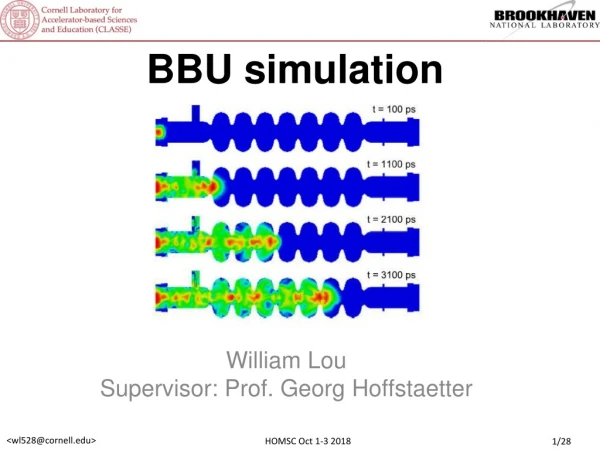
simulation codes: BBU-R and bi BBU-R : developed at JAEA bi : developed at Cornell • tracking code • 2 x 2 matrices for x and y, respectively • x-y decoupled • written in C • 1-loop only • HOM polarization in x, y • tracking code • 4 x 4 matrix for x and y • x-y coupled • written in C++ • multi-loop compatible • arbitrary HOM polarization loop transport see a review paper at ERL05 for further information E. Pozdeyev et al., NIM A 557 (2006) 176-188. M- M M deceleration M- M M+ injection acceleration HOM kick ICFA WS ERL07
Layout of a 5-GeV ERL 5GeV 9cell x 8 QT 9cell x 8 10MeV dump 31 cryomodules 20 MV/m 10MeV injection 0.235 + 1.038 + 0.295 0.295+ 1.038 + 0.235 Q-triplet 0.1 0.1 0.25 0.5 0.25 ICFA WS ERL07
Optics Optimization Optimization scheme -1 (variable K1) • determine all the quad-triplet independently along the linac • and injection twiss-parameters to minimize • beam size (sx, sy) at every cavity • (2) determine the phase advance of the loop to minimize R12, R34 • at every cavity (‘R’ is self-to-self) Optimization scheme -2 (constant K1, known as “graded gradient”) (1) optimize quad-triplet along the linac to maximize Ith (with keeping constant K1 for the lower-energy beam) (2) optimize the phase advance of the loop to maximize Ith ICFA WS ERL07
Results of Optics Optimization (variable K1) 120 3 100 2.5 80 2 60 1.5 40 1 20 0.5 0 0 100 200 300 400 500 600 700 800 900 1000 0 0 5 10 15 20 25 30 deceleration acceleration bx strength of QT : K1 (m-2) bx, by (m) by position of QT z (m) ICFA WS ERL07
Results of Optics Optimization (constant K1) simulation by BI, constant K1 model-1 cavity model-2 cavity Ith (A) Ith (A) Y (deg.) Y (deg.) K1 (m-2) K1 (m-2) linac QT BBU threshold becomes maximum at K1 just below the stability limit of FODO channel. ICFA WS ERL07
Comparison with TESLA cavity 0.7 0.6 0.5 0.4 0.3 0.2 0.1 0 0 50 100 150 200 250 300 350 400 Einj = 10 MeV, Eloop = 5 GeV, Eacc = 20 MV/m ERL Model-2 (HOM: 6x2) threshold current (A) simulation by BI, constant K1 ERL Model-1 (HOM: 6x2) TESLA (HOM: 5x2) phase advance in the ERL loop (deg.) BBU threshold are significantly improved More than 600mA is possible for ERL model-2 cavity ICFA WS ERL07
BBU threshold vs loop length 700 1700 680 660 1650 640 1600 620 1550 600 12700 12750 12800 12850 12900 12950 1500 12700 12750 12800 12850 12900 12950 simulation by BBU-R, variable K1 HOM random = 0 period ~ 3l Ith(mA) 10% strongest HOM f = 4.011GHz loop length (in unit of l/2) HOM random = 1MHz no periodicity 5% Ith(mA) HOM randomization wipes out the periodicity loop length (in unit of l/2) ICFA WS ERL07
Effect of HOM randomization 3 2.5 2 1.5 1 0.5 0 0 0.5 1 1.5 2 Gaussian distribution of HOM frequency is assumed. 10 runs for each randomization. BI (constant K1) BI (variable K1) BBU-R (variable K1) Ith : BBU threshold (A) Ith increases almost linearly with HOM randomization Ith depends on the seed of random number generation, but we can expect Ith > 1 A wtih HOM randomization of 1MHz. HOM randomization (MHz) ICFA WS ERL07
2-loop configuration? J. Bisognano’s talk at FLS-2006. multi-turn -- saves money (construction and operation) -- beams with different energy available -- more compact -- BBU and CSR should be taken care 1-loop An example of a 1-GeV ERL with Qhom~3000 Ith ~ 750mA (1-loop) Ith ~ 300mA (2-loop) 2-loop How realistic is it with the ERL cavities? ICFA WS ERL07
BBU simulation for a 2-loop 5-GeV ERL 0.7 0.6 0.5 0.4 0.3 0.2 0.1 0 0 0.5 1 1.5 2 simulation by BI, constant K1 E (inj) = 10MeV, E (1st-loop) = 2.5GeV E (2nd-loop) = 5GeV Eacc = 20MV/m f bunch = 650MHz 9-cell x 8-cavity x 15-module BBU threshold (A) 1st-loop = 619.994m (2688.5 RF) 2nd-loop = 1020.1015m (4423.5 RF) K1 = 2.3 (m-2) Yx (1st-loop) = 0 Yx (2nd-loop) = 122 deg. 6 x 2 HOMs HOM randomization (MHz) ICFA WS ERL07
beam envelope in the 1st-loop straight (10-cell FODO) simulation by elegant 180-deg. arc (14-cell FODO) 180-deg. arc (14-cell FODO) 2nd loop 1st loop 1st-loop: r=8.66m, 2x14-cell FODO phase advance Yx = 12 p/ 14cell (for compensation of the CSR effect) ICFA WS ERL07
growth of emittance and energy spread 4e-4 1.2 1 3e-4 0.8 0.6 2e-4 0.4 0.2 1e-4 0 0 0.2 0.4 0.6 0.8 1 1.2 0 0 0.2 0.4 0.6 0.8 1 1.2 simulation by elegant emittance growth in the 1-st loop energy-spread induced in the 1-st loop energy spread emittance growth (mm-mrad) 100mA 100mA charge (nC) charge (nC) energy spread due to CSR emittance growth due to CSR see G. Bassi et al. NIM A 557 (2006) 189. ICFA WS ERL07
Summary of HOM-BBU with Model-2 cavity • Threshold current of 5-GeV ERL (10MeV injection, 20MV/m) • Ith ~ 0.6 A (without HOM randomization) • Ith ~ 1.5 A (with 1MHz HOM randomization) • Optics Optimization • variable K1, constant K1 show almost similar Ith • Model-2 Cavity is strong enough for HOM-BBU • 2-loop configuration (2.5GeV x 2) • Ith ~ 0.3 A (1MHz HOM randomization) • CSR effects in the 1st loop are fairly acceptable for a 154pC/3ps bunch • CSR effects are probably acceptable even for a 154pC/1ps bunch ICFA WS ERL07