Download
1 / 34
340 likes | 555 Views
A New Technique for Real-Time Motion Blur Rendering. Steven Lu. Overview. Significance of real-time motion blur rendering (Useful for what?) Slow performance of traditional methods Some of the modern, more efficient methods have problems, too

E N D
A New Technique for Real-Time Motion Blur Rendering Steven Lu
Overview • Significance of real-time motion blur rendering (Useful for what?) • Slow performance of traditional methods • Some of the modern, more efficient methods have problems, too • A new method is presented to address some of these issues, with hardware implementation and real GLSL code
What is Motion Blur? • Motion blur is produced in an image when there is relative motion between subject and camera while the shutter is open • Blur (n.): Something vaguely or indistinctly perceived; something moving or occurring too quickly to be clearly seen • Information contained within an image can be lost if it is blurred. (example: reading a barcode, if you move it across scanner too fast)
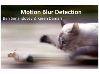
Why motion blur? • Motion blur is a visual cue that the brain uses to perceive and quantify motion • Any kind of streak appears to be in motion • The effect does not even have to be physically accurate to be appreciated • This frame is able to present about a second’s worth of motion
The (expensive) easy way • Naïve implementation: • Render multiple points in time for each frame • The faster something moves, the more times it must be rendered to maintain the same quality • This is definitely the way to go in an offline rendering situation • “Correct” blur is implemented in 2steps: A scene is drawn many times(info gets repeated), then the layers are collapsed & blended (potential info loss)
Too slow! • Rendering a scene more than once per display frame is often not practical • Faster motion = must draw more times • There is little to gain by rendering a scene multiple times • Lots of extra work for slightly improved results
Post-process Fragment Program • Programmable graphics hardware is ubiquitous. We have DirectX 9-class hardware in smartphones and tablets, and Intel IGPs. • Avoid rendering a scene multiple times in order to blur it by using post-process techniques. • Render to texture, and heavily re-sample that texture blur using a pattern dependent on velocity.
The Pixel Velocity Approach • Camera-space velocity at the position of a pixel determines the direction and magnitude of blur. • The depth buffer and inverse view-projection matrix yields the 3D position at each pixel • With this data available for each pixel for both current and previous frame, screen-space 2D pixel velocity field is generated for blur sampling • For more details see GPU Gems 3, Chapter 27: http://http.developer.nvidia.com/GPUGems3/gpugems3_ch27.html
Limitations of Pixel Velocity • Here are some problems with that approach: • Not correct for dynamic geometry (can be addressed) • Incorrect coverage (i.e. sweep distance) • Occlusion: high-velocity object should blur itself only and not its surroundings or what is underneath • Two 4x4 matrix multiplications per pixel. Not prohibitively expensive, but not dirt cheap either: lower bound of 2Gflops. To avoid this, we might use MRT to render a velocity buffer. • But let’s give it some credit: it can account for all types of camera motion because it uses the transformation matrices and adding the effect to an implementation is straightforward.
My Method • I will describe how these issues were addressed during the design of a 2D renderer • Dynamic blurred objects, correct coverage & blending (This is a GIF animation of screen capture)
My Method • Addresses the motion of each object individually • Each final frame composes objects through their actual trajectories • Computes correct coverage & blending for dynamic blurred objects • Looks *really* good with a good physics engine like Box2D. Everything is just more lifelike.
My Method (These are GIF animations of screen capture)
Overview of technical problems • The next 3 slides describe some of the “mechanical” problems that arise when we try to take a single, static render of a scene and try to blend together a dynamic blurred result with it, and how they are dealt with: • Dealing with occlusion • 3D • How limiting to 2D helps us
Coverage and Occlusion • Want to blur the stuff that moves. • Stuff that isn’t moving must stay sharp. • Objects that are opaque will become transparent if they move fast enough. This means traditional Z-test will not work anymore! • It is still possible to have depth testing because opaque regions can be calculated, however every object is now potentially partially or entirely transparent. • The key is to separate overlapping parts of the scene during rendering. I actually use the alpha channel to do this.
Rendering only once is incorrect in general • This cube is rotating in the x-axis and exposes 4 sides to the camera during the frame • Drawing a cube once can only expose 3 sides to the camera • We might cache the previously rendered frame to sample from for our blur?
2D Perks • Each object must be drawn blurred according to its own velocity. Each dynamic object must be drawn in a different layer from what it moves across, to separate the motion of different objectsfrom each other. • In 3D this is a nasty problem to deal with • Not impossible • In most 2D use cases, just draw the background separately from the objects: If the objects do not overlap, we’re good to go.
First attempts at rendering (ca. 2008) • The “obvious” way to implement is to extend with velocity-aware concepts. This principle basically got me all the way to the end. • Per-vertex velocity: varying vec2 vertex attrib • Per-pixel velocity field • This slide is sorely missing renders to illustrate what these implementations look like • The truth is that I skipped over them and didn’t actually write an implementation. My old 2009 demo has a crappy glCopyTexSubImage “deferred rendering” implementation, but like I said, it’s crappy
Taking the idea to its functional extreme • Why stop at a per-pixel vector? • I wanted to make it look exactly like if I did it the expensive way. What was missing?
Taking the idea to its functional extreme • Why stop at a per-pixel vector? • I wanted to make it look exactly like if I did it the expensive way. What was missing? Rotation. Curved Section! 100% Opacity
Taking the idea to its functional extreme • Why stop at a per-pixel vector? • I wanted to make it look exactly like if I did it the expensive way. What was missing? Rotation. Same frames, no blur These are the actual “source” framebuffer-textures to my blurring shader!
Tracing the trajectory • Each pixel samples the texture at positions based on the full trajectory of the object rather than just the tangential velocity. • This allows for the full representation of a rigid planar transformation within the velocity data
Tracing the trajectory • Each pixel samples the texture at positions based on the full trajectory of the object rather than just the surface velocity. • This allows for the full representation of a rigid planar transformation within the velocity data Sample at r + (Θ × r) Θ = αω ta vector Sample at Rot(|Θ|) · r
Tracing the trajectory • Each pixel samples the texture at positions based on the full trajectory of the object rather than just the surface velocity. • This allows for the full representation of a rigid planar transformation within the velocity data Lengths not preserved Correct transformation Transformation incorrect
Data content consumed by shader • 5-component transformation sent to vertex program • Rotation angle = Angular velocity times dt (float) • Rotation center coordinates (vec2) • Linear Translation of center (vec2) • Per-Object quantities! These can be uniforms. • Setting as vertex attributes allows batch drawing on SM3, for SM4 use geometry program to eliminate redundancies. • These values allow the correct sample path “exposed” to each pixel over the “shutter speed” to be calculated by the fragment program.
Implementation • Application built with C++ • Physics simulation – Box2D • Rendering – OpenGL • Shading – GLSL (OpenGL Shading Language) • This is the language used to write code executed on the GPU (this is a separate piece of hardware) CPU GPU GLSL post process Initial conditions Geometry and Shading Data OpenGL Velocity Data Box2D Animated state Normally you finish here
GLSL Shader Code #version 120 uniformmat4projection_mat; uniformmat4modelview_mat; uniformvec2 viewport; attributevec2in_pos; // this is vertex position attributevec2in_center; attributevec4in_vel; // those were the per-object velocity related quantities // I pack omega*dt into in_vel.z, and in_vel.w is max-displacement // for calculating samples attributefloatin_alpha; varyingfloatf_alpha; varyingvec2f_center; varyingvec3f_vel; varyingfloat samples;// # of samples to blur varyingmat2rot_per_sample;// A special scale-rotate matrix varyingvec2f_sceneCoord;// NDC to texcoord void main (void){ mat4proj_modelview_mat=projection_mat*modelview_mat; gl_Position=proj_modelview_mat*vec4(in_pos,0.0,1.0); f_sceneCoord=(gl_Position.xy+vec2(1.0,1.0))*0.5; f_alpha=in_alpha; f_center=((proj_modelview_mat*vec4(in_center,0.0,1.0)).xy +vec2(1.0,1.0))*0.5;// transform the center to clip space f_vel.xy=(proj_modelview_mat*vec4(in_vel.xy,0.0,0.0)).xy*0.5; // velocity also need to be in clip space // careful! We don't shift this one, only scale f_vel.z=in_vel.z;// Store omega in z-comp in radians samples =min(50,(proj_modelview_mat*vec4(in_vel.w,0,0,0)).x *viewport.x*2+1); // w here is not omega it is the max disp value from CPU float theta =in_vel.z/(samples); float cost =cos(theta);floatsint=sin(theta); float aspect =viewport.x/viewport.y; rot_per_sample[0]=vec2(cost,sint*aspect);rot_per_sample[1]=vec2(-sint/aspect,cost); // the rotation matrix is actually a scale and rotate matrix. // the rotation must be correct in world space but is manipulated by the // fragment shader in NDC which requires aspect correction. } #version 120 uniformsampler2D scene; varyingvec2f_sceneCoord;// this should be pretransformedtexcoord to scene tex // it is also appropriate to use as a "this pixel" position // (in relation to center, etc) varyingfloatf_alpha; varyingvec2f_center; varyingvec3f_vel; varyingfloat samples; varyingmat2rot_per_sample; void main (void){ vec2original_center=f_center-f_vel.xy; // vel.xy is actually just the dist vec4accum=vec4(0,0,0,0); mat2cumulativeRotation; // set identity rotation matrix cumulativeRotation[0]=vec2(1,0);cumulativeRotation[1]=vec2(0,1); floatsamples_i=ceil(samples); for(inti=0;i<samples_i;++i){ float fraction =float(i)/samples_i; vec2 pos =cumulativeRotation*(f_sceneCoord+f_vel.xy*fraction-f_center)+f_center; vec4col=texture2D(scene, pos); // 1: translate to origctr 2: rotate by i*rot // 3: translate back to origctr+(curctr-origctr)*i if(abs(col.a-f_alpha)<(1./512.)){accum=accum+vec4(col.rgb,1);} cumulativeRotation=cumulativeRotation*rot_per_sample; } if(accum.a<1.0/1024.)discard;// prevent divide by zero gl_FragColor=vec4(accum.rgb*(1.0/accum.a),accum.a/samples_i); // This should be a non-premultiplied alpha value for use with // saturate blending. }
Conclusions • Issues with existing methods are identified • Solutions are proposed and tested • Motion Blur can and should be implemented as a post-render process • This is very favorable from a performance pov • Can be almost completely “correct” in 2D and very convincing in 3D
Benefits • Speed: 500ns/f @ 800x600 on GTX 260 • Cheap fragment program • Number of samples determined by velocity: Almost zero perf hit on stationary objects!! • Works with multisampling (with careful tweaking for segmentation) • Blur is per-pixel rather than per-fragment, so perf of blur is independent of the number of samples • No additional VRAM requirements, unlike the pixel velocity buffer method. This technique can be applied directly in much the same way a bloom effect might be • Correct for 2D rigid transformations • Theoretically Supports SM2 HW but FBOs help keep it more simple. The good thing is GL ES 2 has FBOs
Shortcomings • Must redesign renderer to separate objects that have different quantities of velocity. • There are also lots of pedantic details to figure out, such as determining the geometry intended for rasterizing the swept area to cover motion: We’re tracing out a curved sample path for each pixel. • Only able to blur things that are visible in the rendering • Cannot sample outside the viewport (demo this, but should put screenshot here) • Occlusion results in overdraw • Applying to arbitrary 3D motion will have artifacts
What’s Next? • Implement in 3D • Non-rigid transformations (soft-bodies)
Q&A? More GIFs I’ll never tire of watching this