Download

1 / 12
120 likes | 237 Views
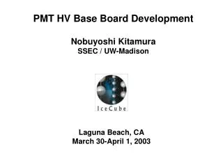
This document summarizes the findings from the PMT HV Base Prototypes Evaluation Workshop held at LBNL on July 23-24, 2003, led by Nobuyoshi Kitamura from the University of Wisconsin-Madison. It discusses three prototypes: the "Old Iseg," "New Iseg" with an isolated ground, and "EMCO," a passive base design. Key results reveal that the "Old Iseg" is cheaper and consumes less power compared to the newer versions while presenting similar noise levels. The document includes testing data and comparisons of performance under various conditions.

E N D
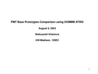
PMT HV Base Prototypes Evaluation Instrumentation Workshop LBNL July 23-24, 2003 Nobuyoshi Kitamura University of Wisconsin-Madison SSEC
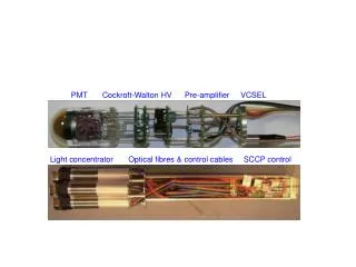
Three prototypes “Old Iseg”—Aug. 2002 prototypes “New Iseg”—Split ground implemented. “EMCO”—Passive base approach consisting of three components: Passive base, HV generator, & digital interface. All designs present the same interface to DOMMB. Jumper pads Passive base Ribbon connector HV generator Digital interface board Jumper pads N. Kitamura 7/23/2003
New Iseg--Isolated Ground Output voltage is unstable with no ground-connecting jumper Data by John Kelly (hv_2000_iseg_psl.pdf) N. Kitamura 7/23/2003
New Iseg with a 1MW Jumper The output voltage is stabilized by installing a jumper. Data by John Kelly (hv_3000_iseg_049.pdf) N. Kitamura 7/23/2003
Connecting Grounds with a Zero W Jumper N. Kitamura 7/23/2003
Connecting Grounds with a 1MW Resister N. Kitamura 7/23/2003
Noise Introduced by Digital Communication This example shows noise from reading the ADC on a new Iseg base with a 1MW jumper. N. Kitamura 7/23/2003
Noise Comparison All the bases have similar random noise levels observed at the secondary side of the signal coupling transformer. *At 50W oscilloscope input using a 50W cable. 100 nsec window (400 pts.) The scope background is 1mVpp, 190mVrms over 100 nsec. N. Kitamura 7/23/2003
Power Dissipation POWER CURRENT (+5V) CURRENT (-5V) “” disableHV N. Kitamura 7/23/2003
Transient Power ISEG OLD Enable after setting DAC to 4095. Measure across 1W. Trigger on “enableHV” ? ISEG NEW EMCO 0.5V, 50nsec N. Kitamura 7/23/2003
Overall Comparison of the Three Prototypes *At 50W oscilloscope input using a 50W cable. 100 nsec window (400 pts.) The scope background is 1mVpp, 190mVrms over 100 nsec. N. Kitamura 7/23/2003
Conclusion Old Iseg or New Iseg? New Iseg with isolated grounds performs badly New Iseg with directly connected grounds performs badly New Iseg with 1MW jumper performs very similarly to Old Iseg Old Iseg is cheaper than New Iseg Old Iseg consumes less power then New Iseg Old Iseg Iseg or EMCO? Both have similar noise levels Vdy1 is fixed in Iseg approach Iseg is cheaper than EMCO Iseg N. Kitamura 7/23/2003