Download
1 / 45
480 likes | 792 Views
What is electric current? What is current measured in? What is the difference between a series and parallel circuit? How many circuit symbols can you draw?. 5.1 Electric Circuits. By the end of today: You should be able to draw circuit symbols for common components.

E N D
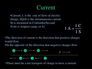
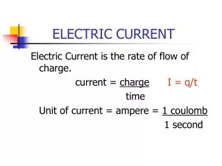
What is electric current? • What is current measured in? • What is the difference between a series and parallel circuit? • How many circuit symbols can you draw?
By the end of today: You should be able to draw circuit symbols for common components. Describe what these things actually do. Some will be able to use these symbols to draw circuit diagrams. 5.1 Electric Circuits
8 1 2 9 3 10 4 11 5 12 6 7 13
By the end of today: You will know where to put an ammeter and a voltmeter in a circuit. You will be able to describe how to measure the resistance of a component. You can state Ohm’s law. Some will be able to rearrange the resistance equation. 5.2 Resistance
R = V I V I R Ohm’s Law Resistance = Potential Difference (volts) (ohms) Current (amperes) V is Potential Difference measured in voltage, V I is current measured in Amps, A R is resistance measured in Ohms, Ω
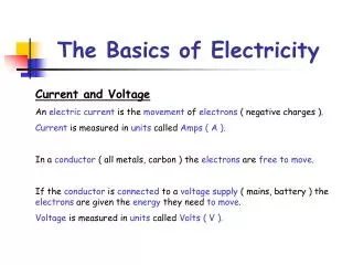
Ohm’s Law The current through a resistor at a constant temperature is directly proportional to the potential difference across the resistor. This means if you double the current you double the voltage over a component. It also means that the resistance of the component does not change when you put more current through it.
By the end of today: You should be able to recognise the graph of current against voltage for a diode, filament lamp, thermistor and LDR 5.3 Resistance of Components
A V • An ammeter measures the current in the circuit • A voltmeter measures the potential difference across a component.
A V
A V
A V How to measure resistance bit of wire http://phet.colorado.edu/en/simulation/circuit-construction-kit-dc
Current (A) Potential Difference (Volts) Current (A) Potential Difference (Volts)
Current (A) R = V I Potential Difference (Volts) A Resistor • If the gradient is constant… • …then the ratio of V to I is constant…. • …so the resistance is constant
A Filament Lamp The filament lamp is a common type of light bulb. It contains a thin coil of wire called the filament. This heats up when an electric current passes through it, and produces light as a result.
A Filament Lamp The filament lamp does not follow Ohm’s Law. Its resistance increases as the temperature of its filament increases. So the current flowing through a filament lamp is not directly proportional to the voltage across it. This is the graph of current against voltage for a filament lamp.
If the diode is this way round, no current can flow so the lamp stays unlit.
A By scientific convention the current goes from the positive end of the battery to the negative end. Conventional Current
A • But current in an electronic circuit is the flow of electrons. • Electrons are negatively charged. • So the electrons actually go the other way around the circuit to what ‘conventional current’ says. Conventional Current
A What is negative current and voltage? • Consider conventional current (+ve to –ve) +ve reading
A What is negative current and voltage? • If we turn the battery around we send the current the other way around the circuit, this gives us a negative reading on the ammeter. -ve reading
The diode has a very high resistance in one direction. This means that current can only flow in the other direction. This is the graph of current against potential difference for a diode.
Thermistors • Thermistors are used as temperature sensors - for example, in fire alarms. Their resistance decreases as the temperature increases: • At low temperatures, the resistance of a thermistor is high and little current can flow through them. • At high temperatures, the resistance of a thermistor is low and more current can flow through them.
Light Dependent Resistor • LDRs are used to detect light levels, for example, in automatic security lights. Their resistance decreases as the light intensity increases: • In the dark and at low light levels, the resistance of an LDR is high and little current can flow through it. • In bright light, the resistance of an LDR is low and more current can flow through it.
Tasks • Use your notes from yesterday to answer Summary Questions 1 and 2 on page 173 • Take detailed notes on a filament lamp and a diode (pg 174). Include a sketch graph of Figure 1 and 2. • Take notes on a thermistor and an LDR (pg 175). Include a sketch graph of Figure 4 and 5. • Answer Summary Questions 1 and 2 on page 175.
Answers • Pg 175 • 1 a) Thermistor • 1 b) Diode • 1 c) Filament Lamp • 1 d) Resistor • 2 a) 15 Ohms • 2 b) Ammeter reading increases because the resistance of the thermistor decreases Pg 173 • 1a) See board • 1b) 6.0 Ohms • 2 • W 6.0 Ohms • X 80 Volts • Y 2.0 Amps • Z 24 Ohms
Extension Tasks • Collect your equipment from my desk. • Can you set up the multimeter to find the resistance of a component? • Draw a superb, artistic, clear diagram of what you have just done. • Measure the resistance of a thermistor and an LDR. • How can you change their resistance? • Does that agree with what you have written in your notes?
Series Circuit The components in the circuit are lined up in series, one after each other.
Parallel Circuit The components in the circuit are lined up in parallel, in parallel lines to one another.
Series Circuit The current (electrons) can only go one way so the current is the same everywhere in the circuit. But the energy it has given to it by the battery is shared equally amongst all the bulbs.
Parallel Circuit The components in the circuit are lined up in parallel, in parallel lines to one another.
Copy this page Resistance of a Circuit R1 R2 The total resistance (known as RT) of a series circuit is equal to the sum of the resistance of each individual component. RT = R1 +R2
Tasks for this lesson… • Answer all summary questions and exam style question on pages 182-183. • Then do the A5 sheet (complete for homework). • Questions with an E are extension questions. If you want an A or an A* then you should have a go at these.
Tasks for this lesson… • Do this sheet first. • Then do this one. • Questions with an E are extension questions. If you want an A or an A* then you should have a go at these.