Download
1 / 4

E N D
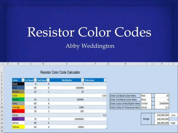
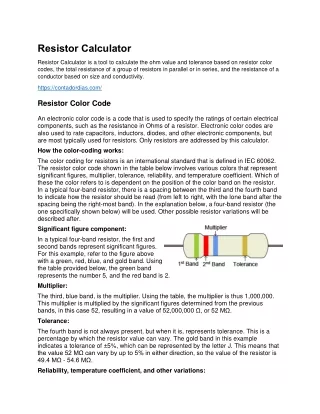
Resistor Calculator Resistor Calculator is a tool to calculate the ohm value and tolerance based on resistor color codes, the total resistance of a group of resistors in parallel or in series, and the resistance of a conductor based on size and conductivity. https://contadordias.com/ Resistor Color Code An electronic color code is a code that is used to specify the ratings of certain electrical components, such as the resistance in Ohms of a resistor. Electronic color codes are also used to rate capacitors, inductors, diodes, and other electronic components, but are most typically used for resistors. Only resistors are addressed by this calculator. How the color-coding works: The color coding for resistors is an international standard that is defined in IEC 60062. The resistor color code shown in the table below involves various colors that represent significant figures, multiplier, tolerance, reliability, and temperature coefficient. Which of these the color refers to is dependent on the position of the color band on the resistor. In a typical four-band resistor, there is a spacing between the third and the fourth band to indicate how the resistor should be read (from left to right, with the lone band after the spacing being the right-most band). In the explanation below, a four-band resistor (the one specifically shown below) will be used. Other possible resistor variations will be described after. Significant figure component: In a typical four-band resistor, the first and second bands represent significant figures. For this example, refer to the figure above with a green, red, blue, and gold band. Using the table provided below, the green band represents the number 5, and the red band is 2. Multiplier: The third, blue band, is the multiplier. Using the table, the multiplier is thus 1,000,000. This multiplier is multiplied by the significant figures determined from the previous bands, in this case 52, resulting in a value of 52,000,000 Ω, or 52 MΩ. Tolerance: The fourth band is not always present, but when it is, represents tolerance. This is a percentage by which the resistor value can vary. The gold band in this example indicates a tolerance of ±5%, which can be represented by the letter J. This means that the value 52 MΩ can vary by up to 5% in either direction, so the value of the resistor is 49.4 MΩ - 54.6 MΩ. Reliability, temperature coefficient, and other variations:
Coded components have at least three bands: two significant figure bands and a multiplier, but there are other possible variations. For example, components that are made to military specifications are typically four-band resistors that may have a fifth band that indicates the reliability of the resistor in terms of failure rate percentage per 1000 hours of service. It is also possible to have a 5th band that is the temperature coefficient, which indicates the change in resistance of the component as a function of ambient temperature in terms of ppm/K. More commonly, there are five-band resistors that are more precise due to a third significant figure band. This shifts the position of the multiplier and tolerance band into the 4th and 5th position as compared to a typical four-band resistor. On the most precise of resistors, a 6th band may be present. The first three bands would be the significant figure bands, the 4th the multiplier, the 5th the tolerance, and the 6th could be either reliability or temperature coefficient. There are also other possible variations, but these are some of the more common configurations. 1st, 2nd, 3rd Color Band Significant Figures Multiplier Tolerance Temperature Coefficient 0 × 1 250 ppm/K (U) Black 1 × 10 ±1% (F) 100 ppm/K (S) Brown 2 × 100 ±2% (G) 50 ppm/K (R) Red 3 × 1K ±0.05% (W) 15 ppm/K (P) Orange 4 × 10K ±0.02% (P) 25 ppm/K (Q) Yellow 5 × 100K ±0.5% (D) 20 ppm/K (Z)
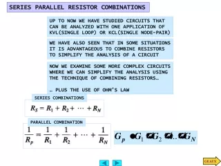
Green 6 × 1M ±0.25% (C) 10 ppm/K (Z) Blue 7 × 10M ±0.1% (B) 5 ppm/K (M) Violet 8 × 100M ±0.01% (L) 1 ppm/K (K) Grey 9 × 1G White × 0.1 ±5% (J) Gold × 0.01 ±10% (K) Silver ±20% (M) None Resistors are circuit elements that impart electrical resistance. While circuits can be highly complicated, and there are many different ways in which resistors can be arranged in a circuit, resistors in complex circuits can typically be broken down and classified as being connected in series or in parallel. Resistors in parallel: The total resistance of resistors in parallel is equal to the reciprocal of the sum of the reciprocals of each individual resistor. Refer to the equation below for clarification: 1 1 R1 R2 R3 Rn Rtotal = 1 1 1 + + + ... +
Resistors in series: The total resistance of resistors in series is simply the sum of the resistances of each resistor. Refer to the equation below for clarification: Rtotal = R1 + R2 + R3 ... + Rn Resistance of a conductor: L A × C R = Where: L is the length of the conductor A is the cross-sectional area of the conductor C is the conductivity of the material