Download

1 / 17
170 likes | 256 Views
The Low-Cost Implement of a Phase Coding SSVEP-Based BCI System. Department of Electrical Engineering National Central University Taiwan. Kuo-Kai Shyu, Po-Lei Lee, Ming-Huan Lee and Yun-Jen Chiu. OUTLINE. I. Introduction II. Material and Methods III. Experimental Results IV. Conclusions.

E N D
The Low-Cost Implement of a Phase Coding SSVEP-Based BCI System Department of Electrical EngineeringNational Central UniversityTaiwan Kuo-Kai Shyu,Po-Lei Lee, Ming-Huan Lee and Yun-Jen Chiu
OUTLINE I. Introduction II. Material and Methods III. Experimental Results IV. Conclusions
I. Introduction • Patients suffering from severe motor disabilities may have limited motion while constrained on a hospital bed. • Therefore, it has to develope a self-care system for patients to control or communicate with external devices can reduce the nursing labor load and facilitate patients’autonomy. • The paper focuses on developing a low-cost steady-state visual-evoked potential (SSVEP) brain-computer interface (BCI) system which can provide a choice for patients to control external devices by measuring their SSVEPs.
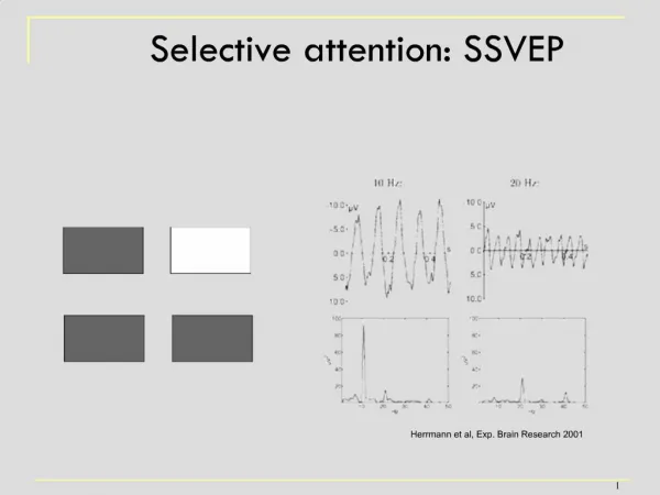
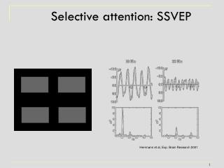
I. Introduction • SSVEP is the presence of EEG periodic signal responses to flickering visual stimuli or flashing light sources (e.g., light-emitting diodes (LEDs) with a frequency higher than 6 Hz [2]. • Main advantages of the SSVEP-based BCI system are higher signal-to-noise ratio (SNR), good information transfer rate (ITR), little training is required, and little electrodes are needed to record the SSVEP. • Most SSVEP-based BCI systems are based on the frequency coding technique. However, in the frequency coding-based BCI system, n different stimuli (commands) need n different flickering frequencies to evoke SSVEPs, thus restricting the number of flashing stimuli.
I. Introduction • Moreover, the amplitude versus frequency response curve for the SSVEP-based system of a subject is nonlinear. Thus it is difficult to arrange multiple flickering frequencies linearly in the frequency coding-base BCI system. • This research chooses the phase coding-based SSVEP for using less frequency to drive multiple stimuli. The proposed SSVEP-based BCI system is based on the phase coding flashing light technique.
II. Material and Methods • System Configuration • The proposed low-cost SSVEP-based BCI system includes: • a handmade stimulation panel, • a customized SSVEP signal preprocessing circuit, • a FPGA-based SSVEP signal processor, and • a bio-feedback speaker.
II. Material and Methods • B. Stimulation Panel • The stimulation panel contains four flickering visual stimuli (multimedia control commands). Each visual stimulus contains one white LED. • Four flashing stimuli are designed based on the phase encoding flashing light technique; four flickering visual stimuli are driven by four phase sequences (0, 90, 180, and 270) at the same flickering frequency, 21 Hz, respectively (stimulus11: 0, stimulus2 2: 90, stimulus3 3: 180, and stimulus4 4: 270).
II. Material and Methods • C. SSVEP Signal Preprocessing Circuit • Three gold-plated EEG electrodes acquire the SSVEP signal from the scalp. Figure 2 illustrates the block diagram of the SSVEP acquisition module board. • The magnitude of the SSVEP signal recorded from the scalp is very small (~50 μV), the SSVEP bipolar signal is first amplified by a pre-amplifier using an instrumentation amplifier, INA128, (Gain setting, Gain: 1000). The INA 128 because it has both high gain and high input impedance, as well as a good common mode rejection ratio (CMRR) (CMRR21Hz: 130dB).
II. Material and Methods • The pre-amplified SSVEP signal is first filtered by a low-pass active second order Butterworth filter (cut-off frequency, fC: 22 Hz) and then filtered by a high-pass one (cut-off frequency, fC: 20 Hz). • To remove power line interference (60 Hz) from SSVEP signals effectively, a 60 Hz notch filter following active filters is used. • The filtered SSVEP signals are amplified again using a post-amplifier circuit (Gain setting, GainMAX: 201) to adjust the filtered SSVEP signals with peak-to-peak voltages in the range of -2.5 to 2.5V. • A DC bias adjustment circuit adjusts voltage level, so that the following SSVEP signal preprocessing circuit easily digitizes SSVEP into the desired range (peak-to-peak : 0–5V).
II. Material and Methods • D. FPGA-based SSVEP Signal Processor • The SSVEP signal-processing algorithm is implemented in the Altera Cyclone EP2C20Q FPGA. • For increasing the numbers calculating precision in FPGA, the hardware floating-point arithmetic units are implemented. • To reduce unwanted signals from the quantified SSVEP signal, a sixth-order IIR band-pass filter is implemented by cascading an IIR low-pass filter and an IIR high-pass filter. The first stage is the third-order IIR low-pass filter and the last stage is the third-order IIR high-pass filter.
II. Material and Methods Based on the phase encoding flashing light technique, the stimulus that the subject is staring at can be recognized by finding the phase of SSVEPAveraged.
III. Experimental Results • Seven subjects (aged 23 to 32 years) with related SSVEPs were recorded using three EEG electrodes. • The reference electrode (SSVEPNEG) was placed at the right mastoid, and the ground electrode (SSVEPGND) was placed at the forehead area. • The subject sat in front of the stimulation panel about 45cm and focused on one of the flickering visual stimuli.
IV. Conclusions • Without using expensive EEG measurement equipments and data acquisition (DAQ) cards, the study designs a SSVEP preprocessing circuit and an ADC module board to acquire and quantify the SSVEP. • The study adopts an FPGA to implement the SSVEP signal processing algorithm and allows on-line processing of the SSVEP signal without the bulky personal computer using commercial signal processing software. • The study designs bio-feedback voice output circuits to the subject. • Experimental results verify effectiveness of the proposed SSVEP-based BCI system. • The proposed SSVEP-based BCI multimedia device control system possibly allows seriously disabled patients to take more care of themselves.