Download
1 / 57
620 likes | 858 Views
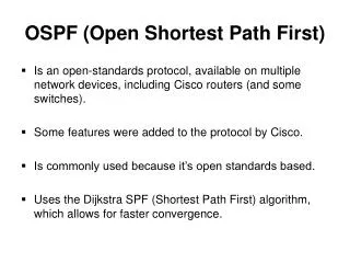
OSPF (Open Shortest Path First). Is an open-standards protocol, available on multiple network devices, including Cisco routers (and some switches). Some features were added to the protocol by Cisco. Is commonly used because it’s open standards based.

E N D
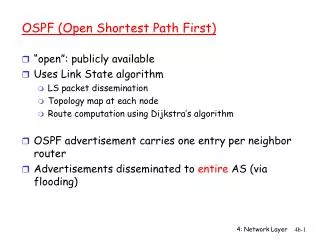
OSPF (Open Shortest Path First) • Is an open-standards protocol, available on multiple network devices, including Cisco routers (and some switches). • Some features were added to the protocol by Cisco. • Is commonly used because it’s open standards based. • Uses the Dijkstra SPF (Shortest Path First) algorithm, which allows for faster convergence.
Introduction • OSPF’s popularity is growing with because of MPLS (Multi Protocol Label Switching). • OSPF and IS-IS are the only routing protocols MPLS has got traffic engineering extensions for. • OSPF v1 is described in RFC 1131 • OSPF v2 is described in RFC 2328 • Only OSPF v2 made it to operational status, but several vendors modified (and modify) OSPF’s characteristics.
Introduction • Within OSPF, links become synonymous with interfaces. • Some of the advantages OSPF has include: • Support for heirarchical network design through the use of areas. • Use of link state databases which reduce the chance of routing loops. • Full support for VLSM (Variable Length Subnet Mask)/Classes routing. • Uses route summarization to reduce the routing table size. • Incremental updates, where routing updates are sent only when a change is made – less bandwidth/CPU used. • Uses multicast packets, so devices not running OSPF are not bothered by those that are. • Supports MD5 authentication, for increased routing security.
OSPF Terminology • These definitions define relationships among routers: • Neighbor: an adjacent router running OSPF with adjacent interfaces assigned to the same area. Neighbors are found via Hello packets. No routing information is exchanged with neighbors until adjacencies are formed. • Adjacency: a logical connection between a router, its corresponding Designated Router (DR) and Backup DR (BDR). Formation of this relation depends heavily on the type of network that connects the OSPF routers.
OSPF Terminology • Link: a network or router interface assigned to any given network. Within OSPF, a link is synonymous with an interface. • Interface: a physical or logical interface on a router. When added to the OSPF process, the interface is considered by OSPF as a link. If the interface is up, the link is up! OSPF uses this association to build its link database. • LSA (Link State Advertisement): an OSPF data packet containing the link state and routing information shared among OSPF routers.
OSPF Terminology • DR: used only when OSPF connects to a BMA (Broadcast Multi Access) network. This reduces the number of adjacencies formed. A DR is elected to disseminate and receive routing information to/from the remaining routers on the BMA network. An example of a BMA network is Ethernet. • BDR: is a hot standby for a DR on the BMA network. The BDR gets all routing updates from OSPF adjacent routers, but doesn’t flood LSA updates Note: A DR and BDR are only available on BMA networks.
OSPF Terminology • OSPF Areas: is similar to EIGRP (Enhanced Interior Gateway Routing Protocol) AS’s (Autonomous Systems). Areas are used to establish a heirarchical network. OSPF uses 4 types of areas. • Internal router: a router with all its interfaces participating in one area. • ABR (Area Border Router): a router with multiple area assignments, where it has several interfaces and if any of those interfaces belong to different areas.
OSPF Terminology • ASBR (Autonomous System Boundary Router): a router with an interface connection to an external network or different AS. An external network or different AS means an interface belongs to a different routing protocol e.g. EIGRP. The ASBR is responsible for injecting routing information learned by another routing protocol, into OSPF. • NBMA (Non-BMA): e.g. Frame Relay, X.25, ATM e.t.c. allows for multi access but has no broadcast ability like Ethernet. NBMA networks need special OSPF configuration to work properly.
OSPF Terminology • BMA: e.g. Ethernet, allow multiple access and provide broadcast ability. A DR and BDR must be elected for BMA networks. • Point-to-Point: comprises a unique NBMA configuration, eliminating the need for DR’s and BDR’s. • Router ID: is an IP address used to identify the router. Cisco chooses the Router ID by using the highest IP of all configured loopback interfaces. If no loopback interfaces are configured, OSPF will choose the highest IP of all configured interfaces on the router.
OSPF Operations • Can be divided into 3 categories: • Neighbor and adjacency initialisation • LSA Flooding • SPF Tree calculation • The basic step-by-step operations of OSPF: • OSPF routers send Hello packets out all interfaces taking part in the OSPF process. If 2 peers agree on the parameters contained in the Hello packet, neighbors are formed. • Some neighbors form adjacencies, which depends on the type of network the Hello packet traverses and the types of routers exchanging the Hello packets.
OSPF Operations • Routers send LSA’s which include the description of the router’s links, and the state of each of link adjacent to the router. • Routers that receive the LSA update their link state databases and forward the LSA’s on to their respective neighbors. This allows all routers taking part in the OSPF process to have the same view of the network. • After learning all the LSA’s, each router runs the Dijkstra SPF algorithm to learn the shortest path to all known destinations. Each router uses this information to create its SPF Tree. The information in the SPT Tree is then populated to the routing table.
OSPF Operations • Note: LSA’s describe the router’s links and the states of those links. • The form and adjacency first • Then flood LSA’s across all OSPF routers • Then calculates shortest path to each router using the Dijkstra SPF algorithm
Neighbor & Adjacency Initialisation • Starts with neighbor/adjacency formation. This is easily formed over point-to-point links. • More complex procedures are needed when several OSPF routers connect via a BMA network. • The Hello protocol is used to discover the neighbors and establish adjacencies. • A Hello packet contains a lot of information about the originating router.
Neighbor & Adjacency Initialisation • By default, the Hello packet multicasts out all interfaces in 10 second intervals. • The Router ID, Area ID and authentication information is carried in a common OSPF header. • Hello packets use a common OSPF header.
OSPF Hello Packet Information • Router ID • Area ID – area to which originating router interface belongs. • Authentication information – type and corresponding information • Network mask – netmask of originating router’s interface IP address • Hello interval – period between Hello packets • Options – OSPF options for neighbor formation • Router priority – 8-bit value that helps in election of the DR and BDR. Is not set on point-to-point links.
OSPF Hello Packet Information • Router Dead Interval – length of time to wait for Hello packet before the neighbor is considered down. Is 4x the Hello interval, unless otherwise. • DR – Router ID of current DR • BDR – Router ID of current BDR • Neighbor Router ID – list of Router ID’s of all the originating router’s neighbors.
Neighbor States • There are 8 states for OSPF neighbors: • Down – no Hello packets have been received from the neighbor. • Attempt – neighbors should be manually configured for this one. It only applies to NBMA networks and shows no recent information received from the neighbor. • Init – Hello packets received from other routers, but the local router hasn’t seen itself in the other routers’ Hello packets. A bi-directional connection hasn’t yet been established. • 2Way – Hello packets with the router’s own Router ID in the Neighbor field is received. Bi-directional traffic communications have now been established. • ExStart – Master/Slave relationship has been established to form an adjacency by exchanging DD (Database Description) packets. The router with the highest Router ID, becomes Master.
OSPF Hello Packet Information • Exchange – routing information is exchanged using the DD and LSR (Link State Request) packets. • Loading – LSR packets are sent to neighbors requesting any new LSA’s that were found while in the “Exchange” state. • Full – all LSA information is synchronized among adjacent neighbors. • Note: on a BMA network, Hello packets are sent out, and each listening router then adds the originating router to its neighbor database. The responding routers will reply with all their Hello information so that the originating router can add them to its own neighbor databse.
OSPF Adjacencies for BMA Networks • 3 types of routers as show: • DR • BDR • DROther • A DROther router belongs to the same network as a DR and BDR other, but don’t represent the network via LSA’s. DROther routers form only 2 adjacencies on a BMA network, with the DR and BDR
BR & BDR Election Process • In BMA, each OSPF interface has a configurable Router Priority. • The default in Cisco is 1. • If you don’t want a router to take part in the election process, set the priority to 0. This is done in interface configuration mode: “ip ospf priority 0”
BR & BDR Election Process • If a DR and BDR already exist on a network, any new comers will accept them regardless of their own Router ID/Priority. • The first router on the network becomes the DR. The next will become with BDR. Other routers will accept these 2 routes as DR and BDR, and form adjacencies with them. • OSPF doesn’t allow pre-empting of a DR when a new comer has a better Router ID/Priority. This allows for better network stability since a router with a higher priority, oscillating from up to down, will not affect the router already selected as the DR
LSA Flooding • Is the method by which OSPF shares its routing information, using LSU (Link State Update) packets. • Using the LSU’s, LSA’s with link state data is shared among all OSPF routers. The network topology is, then, created from these LSA updates. • Flooding is used so that all OSPF routers have the topology map from which SPF calculations can be made. • Efficient flooding is done through the reserved multicast address, 224.0.0.5 (AllSPFRouters).
LSA Flooding • LSA updates, generally, indicate a topology change in the network. • The type of network determines which multicast address is used to send the updates. • Point-to-multipoint networks use the adjacent router’s unicast IP. • The LSA update multicast addresses: • 224.0.0.5 – AllSPFRouters • 224.0.0.6 - AllDR
SPF Tree Calculation • SPF Trees are paths through the network to any given destination. • A separate path for each known destination will exist. There are 2 destination types recognised by OSPF: • Network • Router • Router destinations are specific for ABR’s and ASBR’s. • After all the OSPF routers have synchronized their link state databases, each router is responsible for calculating its SPF Tree for each known destination.
SPF Tree Calculation • The calculation is done using the Dijkstra algorithm. • To perform these calculations, the metrics for each of the links is required.
OSPF Metrics • OSPF uses a metric called “Cost” (E)IGRP = Composite, RIP = Hop Count e.t.c. • Cost is associated with each outgoing interface along an SPF Tree. • The cost of the whole path = the sum of the costs of the outgoing interfaces along that path. • Cisco used its own method of calculating the cost for each OSPF-enabled interface, since cost is an arbitrary value as described in RFC 2328.
OSPF Metrics • Cisco uses the equation: • 108/Bandwidth • Bandwidth = configured bandwidth of the interface (mind the ‘bandwidth’ command). • However, this value can be changed with the interface command “ip ospf cost {1 - 65,535} • Cisco bases the link cost on bandwidth. Other vendors may use other metrics to calculate the link cost. • When using equipment from multiple vendors, ensure the costs match, or you could end up having sub-optimal routing.
OSPF Metrics • Default OSPF costs: • 10Mbps (Ethernet) = 10 • 100Mbps (Fast Ethernet) = 1 • 100Mbps (FDDI) = 1 • T-1 (Serial Interface, 1.544Mbps) = 64 • 56Kbps (Serial Interface, 1.544Mbps default bandwidth) = 64 • HSSI (45Mbps) = 2
NBMA Overview • NBMA networks e.g. Frame Relay and ATM, give OSPF a special challenge. • BMA networks use an election process to select a BR and BDR to represent all OSPF routers on a network. • On NBMA networks, no assurance is given that all connecting devices are getting Hello packets, or are participating in the DR/BDR election. • Because of the difficulty in configuring OSPF on NBMA networks, it’s important to know which configuration/environment is most effective.
NBMA Environments • There are 3 types of networks: • BMA • NBMA – need more configuration for OSPF to work • Point-to-Point • With special configurations on NBMA interfaces, you can cause OSPF to run like it’s on one of the following networks: • Broadcast • Non-broadcast • Point-to-Point • Point-to-Multipoint
NBMA Environments • Know this information: • Broadcast • Hello/Dead Interval = 10/40 (seconds) • Elects DR/BDR = Yes • Non-Broadcast • Hello/Dead Interval = 30/120 (seconds) • Elects DR/BDR = Yes • Point-to-Point • Hello/Dead Interval = 10/40 (seconds) • Elects DR/BDR = No • Point-to-Multipoint • Hello/Dead Interval = 30/120 (seconds) • Elects DR/BDR = No
NBMA Environments • Broadcast: • Default Hello interval is 10 seconds. • Default Dead interval is 4x Hello interval, which is 40 seconds. • Broadcast network will elect a DR and BDR. • To have a broadcast implementation of OSPF on an NBMA network, a full mesh between all the routers is required.
NBMA Environments • Each router has a PVC (Permanent Virtual Circuit) with all the other routers. • This guarantees all routers have a connection to each other and can participate in a DR/BDR election. • Once the election is complete, the meshed network will act as a BMA network. • All LSA’s are sent to the DR and BDR. The DR then floods the updates out every interface. • The problem here is if a PVC (especially between the DR and BDR) fails, connections between other adjacent peers will fail too.
NBMA Environments • Broadcast is the default network type on physical NBMA interfaces. • But this can be changed on any interface in an OSPF process. To configure ‘broadcast’ as a network type for an interface, type: conf t int s0/0 ip ospf network broadcast
NBMA Environments • If this interface command is changed, ensure all other interfaces on that segment have, at least, the same Hello and Dead interval timers, or they won’t work! • It’s recommended, however, that if you change the network type on one interface on a segment, to change all the other routers to match – is suggested, but not required (as long as the Hello and Dead interval timers are matched). • Non-broadcast • All OSPF neighbors should be manually configured (which is the router’s default setting). • Ensures OSPF knows which neighbors need to participate and which neighbor has been identified as a DR.
NBMA Environments • Communications between the neighbors is done via unicast, and not multicast. • This configuration requires a full mesh, and has the same weaknesses as a broadcast environment. • For NBMA networks, the default Hello interval is 30 seconds. • The Dead interval is 4x the Hello interval which is 120 seconds. • NBMA networks also elect a DR and BDR. • To enable a router as a DR, set the priority in the OSPF neighbor statement to elect the neighbor as DR: conf t router ospf 1 neighbor 1.1.1.1 priority {0 – 255}
NBMA Environments • In the neighbor statement, when setting priority, 0 means the router will never become the DR, while 255 means the router has the highest chance of becoming the DR. • To manually configure the network type for non-broadcast: conf t int s0/0 ip ospf network non-broadcast
NBMA Environments • Point-to-Point • Here, you may use sub-interfaces on physical interfaces to create point-to-point connections with other OSPF neighbors. • No DR/BDR is elected since the link is a PPP link. This allows for faster convergence. • A full mesh isn’t required here. • On some sub-interfaces, PVC’s will fail, while on others, they may not, but the OSPF will still be running. • The limitation with this method is inefficient LSA flooding because of several PVC’s per interface; and depending on the PVC mesh, one LSA update can be flooded multiple times.
NBMA Environments • The default Hello interval is 10 seconds. • The Dead interval is 4x the Hello interval which is 40 seconds. • To modify the interface for this method: conf t int s0/0 ip ospf network point-to-point
NBMA Environments • Point-to-Multipoint • Is very similar to point-to-point; no DR/BDR is chosen. • All PVC’s are treated as PPP links, the difference, though, is that all PVC’s lead back to a single router. • Default Hello interval is 30 seconds. • Dead interval is 4x Hello interval, which is 120 seconds. • To change the network type: conf t int s0/0 ip ospf network point-to-multipoint
Interconnecting OSPF Areas • OSPF in a single area has scaling limitations. Multi area OSPF solves this. • All areas need a link to Area 0 (the backbone area). • If an area isn’t attached to Area 0, virtual links can be used to span transit areas in OSPF network.
OSPF Scalability • Each route recalculates its database each time there’s a topology change. This taxes the CPU. • Each router needs to hold a copy of the whole network topology. This taxes memory. • Each router needs a copy of the whole routing table. More memory is, thus, needed. • Recall that the number of entries in the routing (topology) tables may be greater than the number of networks in the routing table.
OSPF Scalability • This is because you have multiple routes to multiple networks. • Essentially, this means that in large networks, single area OSPF will not scale. However, OSPF can be broken down into more manageable areas. • In a multi-area OSPF network, the network becomes very heirarchical. • Routers in a defined area needn’t worry about having a link state database for the whole network. Less memory required,
OSPF Scalability • Routers in an internal area only recalculate the link state database within their area. • Topology changes in one area will not cause global OSPF recalculations. This mean less CPU overhead. • Since route summarization is possible at the area boundary, the routing tables on each of the routers needn’t be as large as they were in a single area.
OSPF LSA Types • Type 1 LSA • Called RLA (Router Link Advertisement) • Sent by router to all other routers in an area • Has information on all router links in the area, including the status and cost for each link. • Routers with connections to multiple areas send a Type 1 LSA to each router it is connected to. • Type 2 LSA • Called NLA (Network Link Advertisement) • Generated by the DR • DR uses this to send information about the state of other routers that are part of the network. • Only sent to routers in the area containing the specific network.
OSPF LSA Types • Type 3 and 4 LSA’s • Called SLA’s (Summary Link Advertisements). • Generated by ABR’s – they send these LSA’s to all routers in an area. • advertise intra-area routes to Area 0. • Advertise both intra and inter-area routes to non-backbone areas. • They only differ between Type 3 and 4: • Type 3 advertises networks outside an area, into an area. • Type 4 advertises information about ASBR’s into an area.
OSPF LSA Types • Type 5 LSA • Called AS ELA (AS External Link Advertisements). • Sent by ASBR’s. • Advertises routes external to the OSPF AS, or the default route to the OSPF AS is reachable through them. • Type 7 LSA • Called NSSA (Not-So-Stubby-Area) external LSA. • Help overcome limitations of an ASBR not being able to belong to a stub area. • Only generated by an ASBR in a NSSA. • The LSA propagates across the area to the ASBR. • When it gets to the ABR, the ABR converts the Type 7 LSA to a Type 5 LSA and propagates it to the backbone. • Advertises routes external to the OSPF AS.
OSPF Virtual Links • When running multi-area OSPF networks, all areas should be connected to Area 0 (backbone area). But sometimes, one area may need to cross one or more other areas to get to Area 0. • This gives rise to virtual links
OSPF Area Types • Stub Area (SA) • Here, an ABR blocks flooding of Type 4 and 5 LSA’s, and instead, generates a Type 3 LSA with the default route for all network external to the AS. • The ABR then floods that and any intra-area Type 3 LSA’s to all internal routers in the (stub) area. • So, all internal routers know that the ABR is the default gateway for traffic external to the stub area. • Totally-Stub-Area (TSA) • Don’t propagate Type 3, 4 and 5 LSA’s, except for one Type 3 LSA that advertises the default route of the area. • The only way a router in the TSA can reach the external AS is through the ABR. • This is a purely Cisco-specific function, and may not be available on other vendors’ equipment.