Download
1 / 167
1.68k likes | 1.93k Views
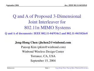
A 3-Dimensional Joint Interleaver for 802.11n MIMO Systems. (Other document used for this presentation: IEEE 802.11-04/1026r0). Jeng-Hong Chen (jhchen2@winbond.com) Pansop Kim (pkim@winbond.com) Winbond Wireless Design Center Torrance, CA, USA September 2004.

E N D
A 3-Dimensional Joint Interleaver for 802.11n MIMO Systems (Other document used for this presentation: IEEE 802.11-04/1026r0) Jeng-Hong Chen (jhchen2@winbond.com) Pansop Kim (pkim@winbond.com) Winbond Wireless Design Center Torrance, CA, USA September 2004 Jeng-Hong Chen, Pansop Kim, Winbond Electronics
Simulation Parameters (based on 11a) • 2X2, 2X3, 2X4, 3X2, 3X3, 3X4, 4X2, 4X3, 4X4 antennas • 11n Channel B, D, E and 11g uncorrelated exponential channel • OFDM based on 11a: 64-pt FFT (only 48 data sub-carriers) • 10% PER over 1000 simulated packets • 1000 un-coded bytes per packet • Perfect CSI, Perfect AFC, AGC, ACQ • No pulse shaping filter, no ADC/DAC • CC rates=1/3,1/2, 2/3,3/4,7/8 from ½ CC code (K=7) with puncturing/repetition • BPSK, QPSK, 16QAM, 64QAM • Interleaver defined in 11a and joint interleaver • 6, 8, 12, 18, 24, 36, 48, 63 Mbps per transmit antenna • MMSE Receiver Jeng-Hong Chen, Pansop Kim, Winbond Electronics
System Models PART-III: Coding Rates & MIMO Tables PART-I: Joint 3D Space-Frequency-Time Interleaver PART-II: Circulation Transmittion (1) OFDM Symbol Based Circulation (2) Sub-carrier Based Circulation Jeng-Hong Chen, Pansop Kim, Winbond Electronics
Challenges of MIMO Interleaver Design • L=Number of OFDM symbols from FEC outputs • NI=Number of OFDM symbols per 3D Joint Interleaver • NOFDM= Number of OFDM symbols are transmitting at the same time • M=Number of transmitter antennas (M NOFDM) • NCBPS=Number of coded bits per OFDM symbol • NSC=Number of data sub-carriers per OFDM symbol • NBPSC=Number of coded bits per sub-carrier • Example: L=18, NI =6, NOFDM =2, M=3, and Nsub=48 (see next page) • How to choose an appropriate interleaver size, NI, for a MIMO system? • How to transmit NOFDM (M) OFDM symbols at the same time from M TX Ant.? • How to interleave total NI*NCBPS coded bits from FEC outputs and map into • NI*Nsub sub-carriers (frequency domain) and various NBPSC for different QAM • M TX antennas (spatial domain) and • NI total OFDM symbols and NOFDM at the same time? Jeng-Hong Chen, Pansop Kim, Winbond Electronics
Example: L=18, NI =6, NOFDM =2, M=3, and Nsub =48 18 OFDM 6 OFDM 6 OFDM 6 OFDM ? Uncoded bits 1 OFDM Time=t9 t8 t7 t6 t5 t4 t3 t2 t1 ? Jeng-Hong Chen, Pansop Kim, Winbond Electronics
PART-I: 3D Joint Interleaver Jeng-Hong Chen, Pansop Kim, Winbond Electronics
Transmitting Total L OFDM Symbols from M TX Antennas Coded bits has L OFDM symbols NI OFDM symbols NI OFDM symbols MIMO Circulation To M TX Antennas • Properties of a MIMO OFDM System: • Diversities include space (antennas),frequency (sub-carrier),and transmission in times • Adjacent coded bits from FEC are highly correlated within dfree bits • Same sub-carrier (frequency domain) from different antennas are correlated • The correlation between adjacent sub-carriers are strongly correlated especially if rms of delay spreading is small. • Purpose of 3D Joint interleaver (Part-II) and Circulation Transmission (Part-III) • Adjacent FEC coded bits are transmitted from nonadjacent sub-carriers and different TX antennas A(k) B(j) 1D output bit stream 1D input bit stream 1-to-1 mapping Jeng-Hong Chen, Pansop Kim, Winbond Electronics
11a Interleaver 11a Interleaver A(K) B(j) • Two-step permutation • First permutation • To ensure that adjacent coded bits are mapped onto nonadjacent subcarriers • Three subcarrier separations between consecutive coded bits • Example: NBPSC=1, NCBPSC=48 Reading order (index of j) Writing order (index of k) • Second permutation (Only applied to 16QAM and 64QAM) • To ensure that adjacent coded bits are mapped alternately onto less and more significant bits Jeng-Hong Chen, Pansop Kim, Winbond Electronics
Parallel 11a Interleavers (A1) • Example: NI=4 ,NBPSC=1, NCBPS=48 • Adjacent bits (ex, A(0), A(1), A(2) and A(3)) are assigned to the same TX antenna. • Interleaver A1 cannot have full benefit from antenna diversity gain if available. Coded bits from FEC outputs Jeng-Hong Chen, Pansop Kim, Winbond Electronics
Parallel 11a Interleavers (A2) • Example: NI=4 ,NBPSC=1, NCBPS=48 • Adjacent bits (ex, A(0), A(1), A(2) and A(3)) are assigned to the same subcarrier. • Interleaver A2 cannot have full benefit from frequency diversity gain if available. Coded bits from FEC outputs Jeng-Hong Chen, Pansop Kim, Winbond Electronics
2D Joint 11a interleaver • Example: NI=4 ,NBPSC=1, NCBPS=48 • First Permutation (the number of rows is NI times.) Writing order (index of k) Reading Order (index of j) • Second Permutation • The same as the 11 a interleaver • Only apply to 16QAM and 64QAM Jeng-Hong Chen, Pansop Kim, Winbond Electronics
2D Joint 11a Interleaver (B1) • Example: NI=4 ,NBPSC=1, NCBPS=48 • Adjacent bits (ex, A(0), A(4),A(8), and A(12).) are assigned to the same subcarrier, • Interleaver B1 cannot have full benefit from frequency diversity gain if available. Jeng-Hong Chen, Pansop Kim, Winbond Electronics
2D Joint 11a Interleaver (B2) • Example: NI=4, NBPSC=1, NCBPS=48 • Adjacent bits (ex, A(0), A(1), A(2),.. and A(15)) are assigned to the same TX ant. • Interleaver B2 cannot have full benefit from antenna diversity gain if available. Jeng-Hong Chen, Pansop Kim, Winbond Electronics
Proposed 3D Joint Interleaver • Purposes • Backward compatible with 11a interleaver and preserve all good properties • To separate consecutive bits by 3*NBPSC or 3 sub-carriers. • To assign consecutive bits to different OFDM symbols • Example: NI=4, NBPSC=1, NCBPS=48 • Rotating the output bits of 2D 11a Joint Interleaver (B2) to different OFDM symbol Jeng-Hong Chen, Pansop Kim, Winbond Electronics
Indexing of Proposed 3D Joint Interleaver k: the index of coded bit before the first permutation i: the index after the first and before the second permutation j: the index after the second permutation, just prior to modulation mapping • First permutation rule where • Second permutation rule where • This interleaver can be easily implemented with 3D block memory Jeng-Hong Chen, Pansop Kim, Winbond Electronics
Input/Output Indexing (BPSK, NI=4, NCBPS=48) Input Index A(k) adjacent FEC coded bits Output Index B(j) different OFDM symbols adjacent 3 sub-carrriers different OFDM symbols Jeng-Hong Chen, Pansop Kim, Winbond Electronics
Input/Output Indexing (QPSK, NI=4, NCBPS=96) Input Index A(k) Output Index B(j) Jeng-Hong Chen, Pansop Kim, Winbond Electronics
Input/Output Indexing (16QAM, NI=4, NCBPS=192) Input Index A(k) Output Index B(j) 2nd Permutation Jeng-Hong Chen, Pansop Kim, Winbond Electronics
Input/Output Indexing (64 QAM, NI=4, NCBPS=288) Input Index A(k) Output Index B(j) 2nd Permutation Jeng-Hong Chen, Pansop Kim, Winbond Electronics
Interleaver Comparisons 3D Interleaver v.s. A1, Channel B, 2x2, 3x3, 4x4 3D Interleaver v.s. A1, Channel E, 2x2, 3x3, 4x4 3D Interleaver v.s. A2, Channel B, 2x2, 3x3, 4x4 3D Interleaver v.s. A2, Channel E, 2x2, 3x3, 4x4 3D Interleaver v.s. B1, Channel B, 2x2, 3x3, 4x4 3D Interleaver v.s. B1, Channel E, 2x2, 3x3, 4x4 3D Interleaver v.s. B2, Channel B, 2x2, 3x3, 4x4 3D Interleaver v.s. B2, Channel E, 2x2, 3x3, 4x4 Jeng-Hong Chen, Pansop Kim, Winbond Electronics
3D Interleaver v.s. A1, Channel B, 2x2 Jeng-Hong Chen, Pansop Kim, Winbond Electronics
3D Interleaver v.s. A1, Channel B, 3x3 Jeng-Hong Chen, Pansop Kim, Winbond Electronics
3D Interleaver v.s. A1, Channel B, 4x4 • Interleaver A1 has smaller space diversity than 3D Interleaver Jeng-Hong Chen, Pansop Kim, Winbond Electronics
3D Interleaver v.s. A1, Channel E, 2x2 Jeng-Hong Chen, Pansop Kim, Winbond Electronics
3D Interleaver v.s. A1, Channel E, 3x3 Jeng-Hong Chen, Pansop Kim, Winbond Electronics
3D Interleaver v.s. A1, Channel E, 4x4 Jeng-Hong Chen, Pansop Kim, Winbond Electronics
3D Interleaver v.s. A2, Channel B, 2x2 Jeng-Hong Chen, Pansop Kim, Winbond Electronics
3D Interleaver v.s. A2, Channel B, 3x3 Jeng-Hong Chen, Pansop Kim, Winbond Electronics
3D Interleaver v.s. A2, Channel B, 4x4 • Interleaver A2 has smaller frequency diversity than 3D Interleaver Jeng-Hong Chen, Pansop Kim, Winbond Electronics
3D Interleaver v.s. A2, Channel E, 2x2 Jeng-Hong Chen, Pansop Kim, Winbond Electronics
3D Interleaver v.s. A2, Channel E, 3x3 Jeng-Hong Chen, Pansop Kim, Winbond Electronics
3D Interleaver v.s. A2, Channel E, 4x4 Jeng-Hong Chen, Pansop Kim, Winbond Electronics
3D Interleaver v.s. B1, Channel B, 2x2 Jeng-Hong Chen, Pansop Kim, Winbond Electronics
3D Interleaver v.s. B1, Channel B, 3x3 Jeng-Hong Chen, Pansop Kim, Winbond Electronics
3D Interleaver v.s. B1, Channel B, 4x4 • Interleaver B1 has smaller frequency diversity than 3D Interleaver Jeng-Hong Chen, Pansop Kim, Winbond Electronics
3D Interleaver v.s. B1, Channel D, 2x2 Jeng-Hong Chen, Pansop Kim, Winbond Electronics
3D Interleaver v.s. B1, Channel D, 3x3 Jeng-Hong Chen, Pansop Kim, Winbond Electronics
3D Interleaver v.s. B1, Channel D, 4x4 Jeng-Hong Chen, Pansop Kim, Winbond Electronics
3D Interleaver v.s. B1, Channel E, 2x2 Jeng-Hong Chen, Pansop Kim, Winbond Electronics
3D Interleaver v.s. B1, Channel E, 3x3 Jeng-Hong Chen, Pansop Kim, Winbond Electronics
3D Interleaver v.s. B1, Channel E, 4x4 Jeng-Hong Chen, Pansop Kim, Winbond Electronics
3D Interleaver v.s. B2, Channel B, 2x2 Jeng-Hong Chen, Pansop Kim, Winbond Electronics
3D Interleaver v.s. B2, Channel B, 3x3 Jeng-Hong Chen, Pansop Kim, Winbond Electronics
3D Interleaver v.s. B2, Channel B, 4x4 • Interleaver B2 has smaller space diversity than 3D Interleaver Jeng-Hong Chen, Pansop Kim, Winbond Electronics
3D Interleaver v.s. B2, Channel E, 2x2 Jeng-Hong Chen, Pansop Kim, Winbond Electronics
3D Interleaver v.s. B2, Channel E, 3x3 Jeng-Hong Chen, Pansop Kim, Winbond Electronics
3D Interleaver v.s. B2, Channel E, 4x4 Jeng-Hong Chen, Pansop Kim, Winbond Electronics
TGn Sync Interleaver (IEEE 802.11-04/889r0) • Ex. 20 MHz, NBPSC=1, NI=4, NCBPS=48, Ncolumn=16 • Note: NSS=4in the definition of above document. • Adjacent bits (ex. A(0), A(1), …, A(11)) are not evenly distributed over all subcarriers • Adjacent bits (ex. A(3),A(6),A(9),A(12)) are assigned to the same subcarrier. • Winbond proposed 3D Joint Interleaver, NBPSC=1, NI=4, NCBPS=48, Ncolumn=16 Jeng-Hong Chen, Pansop Kim, Winbond Electronics
WWiSE Interleaver (IEEE 11-04-0886-00-000n) • Ex. 20 MHz, NBPSC=1, NI=4, NCBPS=54 • Note: NCBPS=216, NSS=NI,IDEPTH=Ncolumn in the definition of above document. • Adjacent bits (ex. A(0), A(1), …, A(11)) are not evenly distributed over subcarriers. • Some adjacent bits (ex. A(21), A(27)) are on the same subcarrier. Jeng-Hong Chen, Pansop Kim, Winbond Electronics
WWiSE Interleaver (IEEE 11-04-0886-00-000n) • Note: Equation (14) in the above doc. has been changed from to to shift Dn subcarriers for NBPSC=1,2,4 and 6. • Winbond proposed 3D Joint Interleaver, NBPSC=1, NI=4, NCBPS=54, Ncolumn=18 Jeng-Hong Chen, Pansop Kim, Winbond Electronics