Download
1 / 4
40 likes | 170 Views
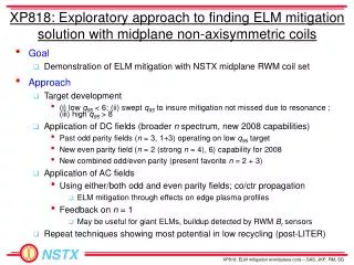
XP818: Exploratory approach to finding ELM mitigation solution with midplane non-axisymmetric coils. Goal Demonstration of ELM mitigation with NSTX midplane RWM coil set Approach Target development

E N D
XP818: Exploratory approach to finding ELM mitigation solution with midplane non-axisymmetric coils • Goal • Demonstration of ELM mitigation with NSTX midplane RWM coil set • Approach • Target development • (i) low q95 < 6; (ii) swept q95 to insure mitigation not missed due to resonance ; (iii) high q95 > 8 • Application of DC fields (broader n spectrum, new 2008 capabilities) • Past odd parity fields (n = 3, 1+3) operating on low q95 target • New even parity field (n = 2 (strong n = 4), 6) capability for 2008 • New combined odd/even parity (present favorite n = 2 + 3) • Application of AC fields • Using either/both odd and even parity fields; co/ctr propagation • ELM mitigation through effects on edge plasma profiles • Feedback on n = 1 • May be useful for giant ELMs, buildup detected by RWM Br sensors • Repeat techniques showing most potential in low recycling (post-LITER)
XP818 ELM Mitigation run on two days last week Task Number of Shots 1) Create target plasmas A) Create q95 < 6 target: (generate at least 10 ELMs with approximately even spacing) (q95 ~ 5.5 is adequate) - Use shot 124349 as setup shot, (Ip = 0.8 MA, Bt = 0.5 T), change NBI source C to 1 MW unmodulated 2 - Raise Ip to 0.9 MA; change Bt to 0.45T, then 0.40T 3 - If q95 > 6 and insufficient ELMs, perform startup optimizations as per J. Menard to raise qmin. (8) B) Create q95 ramp target - Start from low q95 target created in step (1A), Ip flat-top to 0.7 MA, ramping up to 1.0 MA; adjust eventual Ip flat-top if needed to create steady ELMs. 4 - if plasma drops out of H-mode, start Ip ramp from 1.0 MA ramping to 0.7 MA (2) - vary Bt to change range of q ramp (optional) (2) C) Create q95 > 8 target - Use shot 124349 as setup shot, (Ip = 0.8 MA, Bt = 0.5 T), change NBI source C to 1 MW unmodulated - Drop Ip to 0.7 MA; tweak to 0.75 MA if desired 2 2) Attempt ELM mitigation with non-axisymmetric fields under normal recycling conditions - DC fields: A) Apply n = 3 field configuration; vary amplitude from 1.5 kA 4 B) Apply n = 3 + 1 field configuration; vary amplitude from 1.0 kA, 0.5 kA 4 C) Apply n = 2 + 3 field configuration (start from RWM (1-4) 0.5kA, RWM (2,6) 0.5kA, RWM (3,5) 1.5 kA) 4 D) Apply n = 2 field configuration; vary amplitude from 1.5 kA 4 E) Apply n = 6 field configuration (primary field is n = 0); vary amplitude from 2.5 kA 3 - AC fields (pre-programmed): F) Apply n = 3; vary f above/below ELM frequency; vary amplitude from 2.0 kA 4 G) Apply n = 1 (co-propagating); vary f above/below ELM frequency; vary amplitude 4 H) Apply n = 1 (ctr-propagating); vary f above/below ELM frequency; vary amplitude 4 - AC fields (n = 1 feedback): I) n = 1 Br feedback: giant ELM target (e.g. 125271), vary (i) gain (ii) phase 6 3) Attempt ELM mitigation with non-axisymmetric fields under reduced recycling conditions 16 Total (optional): 64 (12) Shots taken (Mon. + Fri.) V1.4
XP818 successful so far in changing ELM frequency • ELM frequency initially reduced with application of AC fields • First shown with n = 3 AC standing wave, then n = 2 AC • AC fields allow application of greater peak RWM coil current before plasma rotation damping becomes too severe • Also shown with DC fields • Jokingly named: “Pulsed High Amplitude Transient” – PHAT ELMs • Longer duration (multi-filament), lower frequency than Type I • Key to now understand the effect - aim for mitigation • Effect is not restricted to a narrow range of q95 – a good thing! • Mitigation in DIII-D shown to be sensitive to q95 • Effect is apparently not highly sensitive to applied field • Clear dependence on field amplitude • Dependence on field configuration (n = odd, even) and application (AC, DC) not yet concluded • Frequency ~ 50Hz largely independent of applied field • Variation of plasma quantity is affecting ELM
Reduced ELM frequency observed in several applied field configurations • Timing of PHAT ELMs correlated to timing of applied field in dedicated shots n = 3 AC field, 70 Hz, 3.8 kA peak-to-peak n = 2 AC field, 70 Hz, 5.5 kA peak-to-peak Ip (kA) IRWM (A) Da(arb) t (s) t (s)