Download
1 / 68
680 likes | 706 Views
Switch contacts (electrical alarm contacts) make or break an electric control circuit dependent upon the position of the instrument pointer. The switch contacts are adjustable over the full extent of the scale range (see DIN 16085), and are mounted predominantly below the dial, though also partly on top of the dial. The instrument pointer (actual value pointer) moves freely across the entire scale range, independent of the setting. Both circular gauges and square panel-mounted gauges feature an adjustment key in the centre of the window. Contacts in flush panel-mounted gauges are adjustable using a screwdriver through the window. Several switch contacts can also be set to at the same setpoint. Contact actuation is made when the actual value pointer travels beyond or below the desired set value.<br>For More Information visit on:- www.seeautomation.com<br>Our Mail I.D:- sales@seeautomation.com<br>Contact Us:- 91-11-22012324 , 8144883403<br>

E N D
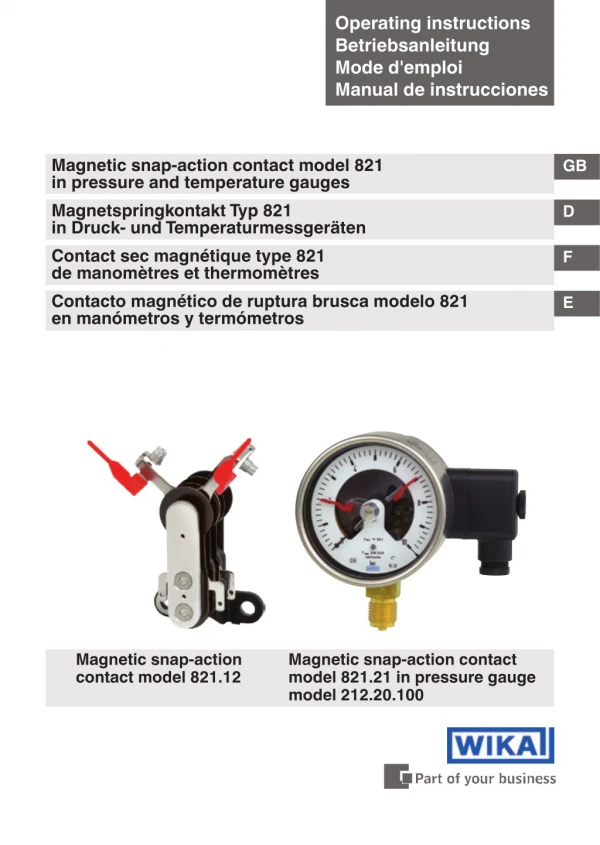
Operating instructions Betriebsanleitung Mode d'emploi Manual de instrucciones Magnetic snap-action contact model 821 in pressure and temperature gauges Magnetspringkontakt Typ 821 in Druck- und Temperaturmessgeräten Contact sec magnétique type 821 de manomètres et thermomètres Contacto magnético de ruptura brusca modelo 821 en manómetros y termómetros GB D F E Magnetic snap-action contact model 821.12 Magnetic snap-action contact model 821.21 in pressure gauge model 212.20.100
Operating instructions model 821 Page 3-18 GB Betriebsanleitung Typ 821 Seite 19-34 D Mode d'emploi type 821 Page 35-50 F Manual de instrucciones modelo 821 Página 51-66 E © 2011 WIKA Alexander Wiegand SE & Co. KG All rights reserved. / Alle Rechte vorbehalten. WIKA® is a registered trademark in various countries. WIKA® ist eine geschützte Marke in verschiedenen Ländern. Prior to starting any work, read the operating instructions! Keep for later use! Vor Beginn aller Arbeiten Betriebsanleitung lesen! Zum späteren Gebrauch aufbewahren! Lire le mode d‘emploi avant de commencer toute opération ! A conserver pour une utilisation ultérieure ! 2003325.03 03/2011 GB/D/F/E ¡Leer el manual de instrucciones antes de comenzar cualquier trabajo! ¡Guardar el manual para una eventual consulta posterior! 2 WIKA operating instructions magnetic snap-action contact model 821
Contents Contents GB 1. 2. 3. 4. General information Safety Specifications Overcurrent protectors Allocation of switch version to basic instruments and measuring ranges Design and function Transport, packaging and storage Commissioning, operation Contact protection measures Maintenance and cleaning Dismounting and disposal 4 5 8 10 11 5. 6. 7. 8. 9. 10. 11. 12 12 13 15 18 18 2003325.03 03/2011 GB/D/F/E 3 WIKA operating instructions magnetic snap-action contact model 821
1. General information 1. General information ■ The magnetic snap-action contact described in the operating instructions has been designed and manufactured by state-of-the- art knowledge. All components are subject to stringent quality and environmental criteria during production. Our management systems are certified to ISO 9001 and ISO 14001. GB ■ These operating instructions contain important information on handling the magnetic snap-action contact. Working safely requires that all safety instructions and work instructions are observed. ■ Observe the relevant local accident prevention regulations and general safety regulations for the magnetic snap-action's range of use. ■ The operating instructions are part of the product and must be kept in the immediate vicinity of the instruments with magnetic snap-action contacts and readily accessible to qualified personnel at any time. ■ Skilled personnel must have carefully read and understood the operating instructions prior to beginning any work. ■ The manufacturer's liability is void in the case of any damage caused by using the product contrary to its intended use, non-compliance with these operating instructions, assignment of insufficiently qualified skilled personnel or unauthorised modifications to the instrument. ■ The general terms and conditions, contained in the sales documentation, shall apply. ■ Subject to technical modifications. 2003325.03 03/2011 GB/D/F/E ■ Further information: - Internet address: - Application consultant: www.wika.de / www.wika.com Tel.: (+49) 9372/132-0 Fax: (+49) 9372/132-406 E-Mail: info@wika.de 4 WIKA operating instructions magnetic snap-action contact model 821
1. General information / 2. Safety Explanation of symbols WARNING! ... indicates a potentially dangerous situation that can result in serious injury or death, if not avoided. GB Information … points out useful tips, recommendations and information for efficient and trouble-free operation. 2. Safety WARNING! Before installation, commissioning and operation, ensure that the appropriate magnetive snap-action contact has been selected in terms of design and specific measuring conditions. The instruments are no safety accessories as defined by the pressure equipment directive 97/23/EC. Non-observance can result in serious injury and/or damage to the equipment. Further important safety instructions can be found in the individual chapters of these operating instructions. 2003325.03 03/2011 GB/D/F/E 5 WIKA operating instructions magnetic snap-action contact model 821
2. Safety 2.1 Intended use The model 821 magnetic snap-action contact is used for the switching of switching currents up to max. 1 A. GB The magnetic snap-action contact has been designed and built solely for the intended use described here and may only be used accordingly. The manufacturer shall not be liable for claims of any type based on operation contrary to the intended use. 2.2 Personnel qualification WARNING! Risk of injury if qualification is insufficient! Improper handling can result in considerable injury and damage to equipment. may only be carried out by skilled personnel who have the qualifications described below. ■ The activities described in these operating instructions Skilled personnel Skilled personnel are understood to be personnel who, based on their technical training, knowledge of measurement and control technology and on their experience and knowledge of country-specific regulations, current standards and directives, are capable of carrying out the work described and of independently recognising potential hazards. 2.3 Special hazards 2003325.03 03/2011 GB/D/F/E WARNING! When installing, commissioning and operating these instru- ments, observe the appropriate national safety regulations (e.g. VDE 0100). 6 WIKA operating instructions magnetic snap-action contact model 821
2. Safety WARNING! Only work on the gauge with the voltage disconnected. GB WARNING! Residual media in dismounted instruments can result in a risk to persons, the environment and equipment. Take sufficient precautionary measures. 2.4 Labelling / Safety marks Product label Date of manufacture Explanation of symbols Before mounting and commissioning the magnetic snap- action contact, ensure you read the operating instructions! CE, Communauté Européenne Instruments bearing this mark comply with the relevant european directives. 2003325.03 03/2011 GB/D/F/E Instruments bearing this mark on the dial are safety pressure gauges with solid baffle wall per EN 837 (S3). 7 WIKA operating instructions magnetic snap-action contact model 821
3. Specifications 3. Specifications Table 1a: Limits for the magnetic snap-action contact model 821 Limits for the contact rating with resistive load Magnetic snap-action contact model 821 dry gauges GB filled gauges Rated voltage Ueff max. Rated current 1) Make current Breaking current Continuous current Contact rating max. 250 V 250 V 1.0 A 1.0 A 0.6 A 30 W / 50 VA 1.0 A 1.0 A 0.6 A 20 W / 20 VA Table 1b: Limits for the sliding contact model 811 Limits for the contact rating with resistive load Rated voltage Ueff max. Rated current 1) Make current Breaking current Continuous current Contact rating max. Sliding contact model 811 dry gauges 250 V 0.7 A 0.7 A 0.6 A 10 W / 18 VA 1) The values for rated currents shown in the above table apply to instruments with switch ver- sion S. For instruments with switch version L these values should be halved. (see chapter "5. Allocation of switch version to basic instruments and measuring ranges") WARNING! None of the limits for voltage, current and power are to be exceeded! We recommend the following load values to ensure safe, continuous operation: 2003325.03 03/2011 GB/D/F/E 8 WIKA operating instructions magnetic snap-action contact model 821
3. Specifications Table 2a: Recommended contact rating for the magnetic snap-action contact model 821 Voltage (DIN IEC 38) DC / AC Magnetic snap-action contact model 821 dry gauges resistive load DC mA mA mA 100 120 65 200 240 130 300 450 200 400 600 250 Table 2a: Recommended contact rating for the sliding contact model 811 filled gauges resistive load DC mA 65 130 190 250 GB inductive load cos ϕ >0.7 mA 40 85 130 150 inductive load cos ϕ >0.7 AC mA 90 180 330 450 AC V 230 110 48 24 Voltage (DIN IEC 38) DC / AC Sliding contact model 811 dry gauges resistive load DC mA 40 80 120 200 The switching current must not be less than 20 mA with low voltages for switching reliability reasons. For higher loads, and instruments with liquid-filled cases, we recommend using WIKA contact protection relays, models 905.1x. inductive load cos ϕ >0.7 mA 25 45 70 100 AC mA 45 90 170 350 V 230 110 48 24 The ingress protection to EN 60529 against external influences depends on the basic instrument and is found in the respective data sheet. The limit switches can be used in the range from -20 to +70 °C. Where the permissible temperatures for the basic instrument (see data sheet) deviate from this range, the lower values are valid. 2003325.03 03/2011 GB/D/F/E For further specifications see the corresponding WIKA data sheet and the order documentation. 9 WIKA operating instructions magnetic snap-action contact model 821
4. Overcurrent protectors 4. Overcurrent protectors The instruments do not provide for incorporated overcurrent protectors. Should protectors be required, we recommend the following values in accordance with EN 60947-5-1. GB Table 3a: Overcurrent protectors with magnetic snap-action contact Voltage Magnetic snap-action contact model 821 Switch version S 1) Switch version L 1) Nominal size of instrument 63 100 Nominal size of instrument 63 100 1 A 0.315 A 0.63 A 160 160 1 A 0.63 A V 24 250 1 A 0.63 A 2 A 1 A 2 A 1 A 0.63 A Table 3b: Overcurrent protectors with sliding contact Voltage Sliding contact model 811 Switch version S 1) Switch version L 1) Nominal size of instrument 63 100 1 A 0.125 A 0.315 A Nominal size of instrument 63 100 0.315 A 0.63 A 0.063 A 0.125 A 160 1 A 0.315 A 160 V 24 250 0.63 A 0.63 A 0.125 A All data refer to miniature fuses M and a maximum short circuit current of 100 A. 1) see chapter "5. Allocation of switch version to basic instruments and measuring ranges". 2003325.03 03/2011 GB/D/F/E 10 WIKA operating instructions magnetic snap-action contact model 821
5. Allocation of switch version to basic instruments ... 5. Allocation of switch version to basic instruments and measuring ranges Depending on the basic instrument model, measuring range and number of limit switches the switch versions S and L are used. The following table 4 shows the model 2 instruments with the allocated switch version L. GB Table 4: Allocation of switch version to basic instruments and measuring ranges Nominal size Number of contacts Measuring spans Switch version WIKA basic instrument model 2xx.xx 2xx.xx 2xx.xx 2xx.xx 214.11 214.11 214.11 214.11 100 and 160 100 and 160 100 160 96x96 and 144x144 1 96x96 and 144x144 2 96x96 144x144 1 2 3 or 4 3 or 4 ≤ 1 bar ≤ 1.6 bar ≤ 4 bar ≤ 2.5 bar ≤ 1 bar ≤ 1.6 bar ≤ 4 bar ≤ 2.5 bar L L L L L L L L 3 3 All other model 2 instruments are manufactured with switch version S. For model 3, 4, 5, 6 and 7 as well as model 55 and 73 instruments switch version L is used. 2003325.03 03/2011 GB/D/F/E 11 WIKA operating instructions magnetic snap-action contact model 821
6. Design and function / 7. Transport, packaging ... 6. Design and function 6.1 Description The built-in electrical switch contacts (magnetic snap-action or sliding contacts) are auxiliary current switches which open or close connected electric circuits at the set limits via the contact arm which is moved by the actual value pointer. GB 6.2 Scope of delivery Cross-check scope of delivery with the delivery note. 7. Transport, packaging and storage 7.1 Transport Check the instrument for any damage that may have been caused during transportation. Obvious damage must be reported immediately. 7.2 Packaging Do not remove packaging until just before mounting. Keep the packaging as it will provide optimum protection during trans- port (e.g. change in installation site, sending for repair). 7.3 Storage Permissible conditions at the place of storage: Storage temperature: In accordance with measuring instrument 2003325.03 03/2011 GB/D/F/E 12 WIKA operating instructions magnetic snap-action contact model 821
8. Commissioning, operation 8. Commissioning, operation 8.1 Mechanical connection In accordance with the general technical regulations for pressure gauges (e.g. EN 837-2 "Selection and installation recommendations for pressure gauges" and/or EN 13190 "Dial indicating thermometers"). GB When screwing gauges in, the force required for this must not be applied through the case or the cable terminal box, but rather through the spanner flats (using a suitable tool) provided for this purpose on the square shaft of standard connections. Installation with open-ended spanner Correct sealing of pressure gauge connections with parallel threads must be made using suitable sealing rings, sealing washers or WIKA profile seals. The sealing of tapered threads (e.g. NPT threads) is made by providing the thread , with additional sealing material such as, for example, PTFE tape (EN 837-2). Sealing in the thread Spanner flats Sealing face The torque depends on the seal used. Connecting the gauge using a clamp socket or a union nut is recommended, so that it is easier to orientate the gauge correctly. When a blow-out device is fitted to a pressure gauge, it must be protected against being blocked by debris and dirt. 2003325.03 03/2011 GB/D/F/E 13 WIKA operating instructions magnetic snap-action contact model 821
8. Commissioning, operation With safety pressure gauges (see dial symbol k) ensure that the free space behind the blow-out back is at least 15 mm. 8.2 Special requirements for the installation point The instruments must be mounted in a location free from vibration in order to avoid contact chatter and the resulting increased wear. If the line to the measuring instrument is not adequately stable, a measuring instrument holder should be used for fastening (and possibly via a flexible capillary). If vibrations cannot be avoided by means of suitable instal- lation, instruments with liquid filling should be used. The instruments should be protected against coarse dirt and wide fluctuations in ambient temperature. GB 8.3 Electrical connection The electrical connection must only be made by qualified skilled personnel. Connection details and switching functions are given on the product label. Connection terminals and earth terminal are appro- priately marked. The mains connection lines to be provided must be dimensioned for maximum instrument power consumption and comply with IEC 227 or IEC 245. Power ratings (see "Specifications") and protective circuits with inductive and capacitive loads see chapter "9. Contact protection measures". 2003325.03 03/2011 GB/D/F/E 14 WIKA operating instructions magnetic snap-action contact model 821
8. Commisioning, operation / 9. Contact protection ... 8.4 Adjusting the set pointers The setting of the set points is achieved using the adjustment lock in the window with the aid of the adjustment key (part of the scope of delivery; found in standard instruments on the side of the terminal box). GB Set pointer Removable adjustment key Adjustment lock The set pointers for the limit switches are freely adjustable over the full scale range. For reasons of switching accuracy, switching reliability and service life of the mechanical measuring systems, the switch points should be between 10 % and 90 % of the measuring span. Commissioning During the commissioning process pressure surges must be avoided at all costs. Open the shut-off valves slowly. 9. Contact protection measures Mechanical contacts must not exceed the specified electrical values for switching current and switching voltage independent of each other, not even for a short time only. For capacitive or inductive loads we recommend one of the following protective circuits: 2003325.03 03/2011 GB/D/F/E 15 WIKA operating instructions magnetic snap-action contact model 821
9. Contact protection measures 9.1. Inductive load with DC voltage With DC voltage the contact protection can be achieved via a free- wheeling diode, connected in parallel to the load. The polarity of the diode must be arranged so that it closes when the operating voltage is on. GB Example: Contact protection measure with free- wheeling diode Contact Diode 9.2. Inductive load with AC voltage With AC voltage two protection measures are possible: Contact Example: Contact protec- tion measure with voltage-depend- ent resistor VDR Contact Example: Contact protection measure with RC element 2003325.03 03/2011 GB/D/F/E 16 WIKA operating instructions magnetic snap-action contact model 821
9. Contact protection measures 9.3. Capacitive load With capacitive loads elevated switch-on currents arise. These can be reduced by series-connecting resistors in the supply line. GB Contact Examples: Contact protec- tion measure with current-limiting resistor Contact Contact curve The hatched area of the contact curve shows the permissible electrical values for the respective contact. Accordingly the voltage and/or current to be switched must not exceed the respective maximum values. The power to be switched may only lie below the limit curve. V max. voltage Vmax Switching voltage limit curve allowed working range 2003325.03 03/2011 GB/D/F/E max. current Vmin A Amin Switching current Amax 17 WIKA operating instructions magnetic snap-action contact model 821
10. Maintenance and cleaning / 11. Dismounting and ... 10. Maintenance and cleaning 10.1 Maintenance The instruments are maintenance-free. The indicator and switching function should be checked once or twice every year. For this the instrument must be disconnected from the process to check with a pressure or temperature testing device. Repairs must only be carried out by the manufacturer or appropriately qualified skilled personnel. GB 10.2 Cleaning CAUTION! returning it, in order to protect personnel and the environment from exposure to residual media. ■ Clean the instrument with a moist cloth. ■ Wash or clean the dismounted instrument before 11. Dismounting and disposal WARNING! Residual media in dismounted pressure or temperature measuring instruments can result in a risk to persons, the environment and equipment. Take sufficient precautionary measures. 11.1 Dismounting Only disconnect the instrument once the system has been depressurised! When dismounting, close the compensating valve (if available). Risk of burns with temperature measuring instrument! Let the instrument cool down sufficiently before dismounting! During dismounting there is a risk of dangerously hot pressure media escaping. 2003325.03 03/2011 GB/D/F/E 11.2 Disposal Incorrect disposal can put the environment at risk. Dispose of instrument components and packaging materials in an environmentally compatible way and in accordance with the country-specific waste disposal regulations. 18 WIKA operating instructions magnetic snap-action contact model 821
Inhalt Inhalt 1. 2. 3. 4. Allgemeines Sicherheit Technische Daten Überstrom-Schutzeinrichtungen Zuordnung Schalterversion zu Grundgeräten und Messbereichen Aufbau und Funktion Transport, Verpackung und Lagerung Inbetriebnahme, Betrieb Kontaktschutzmaßnahmen Wartung und Reinigung Demontage und Entsorgung 20 21 24 26 27 D 5. 6. 7. 8. 9. 10. 11. 28 28 29 31 34 34 2003325.03 03/2011 GB/D/F/E 19 WIKA Betriebsanleitung Magnetspringkontakt Typ 821
1. Allgemeines 1. Allgemeines ■ Der in der Betriebsanleitung beschriebene Magnetspringkontakt wird nach den neuesten Erkenntnissen konstruiert und gefertigt. Alle Komponenten unterliegen während der Fertigung strengen Qualitäts- und Umweltkriterien. Unsere Managementsysteme sind nach ISO 9001 und ISO 14001 zertifiziert. D ■ Diese Betriebsanleitung gibt wichtige Hinweise zum Umgang mit dem Magnetspringkontakt. Voraussetzung für sicheres Arbeiten ist die Einhaltung aller angegebenen Sicherheitshinweise und Handlungsanweisungen. ■ Die für den Einsatzbereich des Magnetspringkontaktes geltenden örtlichen Unfallverhütungsvorschriften und allgemeinen Sicherheits- bestimmungen einhalten. ■ Die Betriebsanleitung ist Produktbestandteil und muss in unmit- telbarer Nähe des Gerätes mit Magnetspringkontakten für das Fachpersonal jederzeit zugänglich aufbewahrt werden. ■ Das Fachpersonal muss die Betriebsanleitung vor Beginn aller Arbeiten sorgfältig durchgelesen und verstanden haben. ■ Die Haftung des Herstellers erlischt bei Schäden durch bestim- mungswidrige Verwendung, Nichtbeachten dieser Betriebsanleitung, Einsatz ungenügend qualifizierten Fachpersonals sowie eigenmäch- tiger Veränderung am Gerät. ■ Es gelten die allgemeinen Geschäftsbedingungen in den Verkaufs- unterlagen. ■ Technische Änderungen vorbehalten. 2003325.03 03/2011 GB/D/F/E ■ Weitere Informationen: - Internet-Adresse: - Anwendungsberater: www.wika.de / www.wika.com Tel.: (+49) 9372/132-0 Fax: (+49) 9372/132-406 E-Mail: info@wika.de 20 WIKA Betriebsanleitung Magnetspringkontakt Typ 821
1. Allgemeines / 2. Sicherheit Symbolerklärung WARNUNG! … weist auf eine möglicherweise gefährliche Situation hin, die zum Tod oder zu schweren Verletzungen führen kann, wenn sie nicht gemieden wird. D Information … hebt nützliche Tipps und Empfehlungen sowie Informationen für einen effizienten und störungsfreien Betrieb hervor. 2. Sicherheit WARNUNG! Vor Montage, Inbetriebnahme und Betrieb sicherstellen, dass der richtige Magnetspringkontakt hinsichtlich Ausfüh- rung und spezifischen Messbedingungen ausgewählt wurde. Die Geräte sind keine Ausrüstungsteile mit Sicherheitsfunk- tion im Sinne der Druckgeräterichtlinie 97/23/EG. Bei Nichtbeachten können schwere Körperverletzungen und/oder Sachschäden auftreten. Weitere wichtige Sicherheitshinweise befinden sich in den einzelnen Kapiteln dieser Betriebsanleitung. 2003325.03 03/2011 GB/D/F/E 21 WIKA Betriebsanleitung Magnetspringkontakt Typ 821
2. Sicherheit 2.1 Bestimmungsgemäße Verwendung Der Magnetspringkontakt Typ 821 dient zum Schalten von Schaltströ- men bis max. 1 A. Der Magnetspringkontakt ist ausschließlich für den hier beschriebenen bestimmungsgemäßen Verwendungszweck konzipiert und konstruiert und darf nur dementsprechend verwendet werden. D Ansprüche jeglicher Art aufgrund von nicht bestimmungsgemäßer Verwendung sind ausgeschlossen. 2.2 Personalqualifikation WARNUNG! Verletzungsgefahr bei unzureichender Qualifikation! Unsachgemäßer Umgang kann zu erheblichen Personen- und Sachschäden führen. Tätigkeiten nur durch Fachpersonal nachfolgend beschriebener Qualifikation durchführen lassen. ■ Die in dieser Betriebsanleitung beschriebenen Fachpersonal Das Fachpersonal ist aufgrund seiner fachlichen Ausbildung, seiner Kenntnisse der Mess- und Regelungstechnik und seiner Erfahrungen sowie Kenntnis der landesspezifischen Vorschriften, geltenden Normen und Richtlinien in der Lage, die beschriebenen Arbeiten auszuführen und mögliche Gefahren selbstständig zu erkennen. 2.3 Besondere Gefahren 2003325.03 03/2011 GB/D/F/E WARNUNG! Bei Montage, Inbetriebnahme und Betrieb dieser Geräte unbedingt die entsprechenden nationalen Sicherheitsvor- schriften (z. B. VDE 0100) beachten. 22 WIKA Betriebsanleitung Magnetspringkontakt Typ 821
2. Sicherheit WARNUNG! Alle Arbeiten dürfen nur im spannungslosen Zustand erfolgen. WARNUNG! Messstoffreste in ausgebauten Geräten können zur Gefähr- dung von Personen, Umwelt und Einrichtung führen. Ausreichende Vorsichtsmaßnahmen ergreifen. D 2.4 Beschilderung / Sicherheitskennzeichnungen Typenschild Herstellungsdatum Symbolerklärung Vor Montage und Inbetriebnahme des Gerätes mit Magnet- springkontakten unbedingt die Betriebsanleitung lesen! CE, Communauté Européenne Geräte mit dieser Kennzeichnung stimmen überein mit den zutreffenden europäischen Richtlinien. 2003325.03 03/2011 GB/D/F/E Geräte mit dieser Kennzeichnung auf dem Zifferblatt sind Sicherheitsdruckmessgeräte mit bruchsicherer Trennwand nach EN 837 (S3). 23 WIKA Betriebsanleitung Magnetspringkontakt Typ 821
3. Technische Daten 3. Technische Daten Tabelle 1a: Grenzwerte für Magnetspringkontakt Typ 821 Grenzwerte für die Kontaktbelastung bei ohmscher Belastung Nennbetriebsspannung Ueff max. Nennbetriebsstrom 1) Einschaltstrom Ausschaltstrom Dauerstrom Schaltleistung max. Magnetspringkontakt Typ 821 ungefüllte Geräte gefüllte Geräte D 250 V 250 V 1,0 A 1,0 A 0,6 A 30 W / 50 VA 1,0 A 1,0 A 0,6 A 20 W / 20 VA Tabelle 1b: Grenzwerte für Schleichkontakt Typ 811 Grenzwerte für die Kontaktbelastung bei ohmscher Belastung Nennbetriebsspannung Ueff max. Nennbetriebsstrom 1) Einschaltstrom Ausschaltstrom Dauerstrom Schaltleistung max. Schleichkontakt Typ 811 ungefüllte Geräte 250 V 0,7 A 0,7 A 0,6 A 10 W / 18 VA 1) Die angegebenen Werte für die Nennbetriebsströme gelten für die Geräteausführungen mit Schalterversion S. Für die Version L sind diese Werte zu halbieren. (siehe Kapitel "5. Zuordnung Schalterversion zu Grundgeräten und Messbereichen") WARNUNG! Es darf keiner der Grenzwerte für Spannung, Strom und Leistung überschritten werden! Um die sichere Funktion auf Dauer zu gewährleisten, empfehlen wir folgende Belastungswerte: 2003325.03 03/2011 GB/D/F/E 24 WIKA Betriebsanleitung Magnetspringkontakt Typ 821
3. Technische Daten Tabelle 2a: Empfohlene Kontaktbelastung für Magnetspringkontakt Typ 821 Spannung (DIN IEC 38) DC / AC Magnetspringkontakt Typ 821 ungefüllte Geräte ohmsche Belastung DC mA mA 100 120 200 240 300 450 400 600 Tabelle 2b: Empfohlene Kontaktbelastung für Schleichkontakt Typ 811 gefüllte Geräte ohmsche Belastung DC mA 65 130 190 250 induktive Belastung cos ϕ >0,7 mA 40 85 130 150 induktive Belastung cos ϕ >0,7 mA 65 130 200 250 AC mA 90 180 330 450 AC V 230 110 48 24 D Spannung (DIN IEC 38) DC / AC Schleichkontakt Typ 811 ungefüllte Geräte ohmsche Belastung DC mA 40 80 120 200 Bei niedrigen Spannungen darf der Schaltstrom aus Gründen der Schaltsicherheit nicht kleiner als 20 mA sein. Für höhere Belastungen sowie für Geräte mit flüssigkeits- gefüllten Gehäusen empfehlen wir die WIKA-Kontakt- schutzrelais Typen 905.1x. Die Schutzart nach EN 60529 gegen äußere Einflüsse hängt vom Grundgerät ab und ist dem entsprechenden Datenblatt zu entnehmen. Die Grenzwertschalter können im Umgebungstemperaturbereich von -20 bis +70 °C eingesetzt werden. Falls die für das Grundgerät zugelassenen Temperaturen (siehe Datenblatt) diesen Bereich eingrenzen, gelten die eingeschränkten Werte. induktive Belastung cos ϕ >0,7 mA 25 45 70 100 AC mA 45 90 170 350 V 230 110 48 24 2003325.03 03/2011 GB/D/F/E Weitere technische Daten siehe jeweiliges WIKA Datenblatt und Bestellunterlagen. 25 WIKA Betriebsanleitung Magnetspringkontakt Typ 821
4. Überstrom-Schutzeinrichtungen 4. Überstrom-Schutzeinrichtungen In den Geräten sind keine Überstrom-Schutzeinrichtungen eingebaut. Falls Schutzeinrichtungen gefordert werden, empfehlen wir dafür folgende Werte nach EN 60947-5-1. Tabelle 3a: Überstrom-Schutzeinrichtungen bei Magnetspringkontakt Spannung Magnetspringkontakt Typ 821 Schalterversion S 1) D Schalterversion L 1) Geräte-Nenngröße 63 Geräte-Nenngröße 63 100 160 100 1 A 0,63 A 160 1 A 0,63 A V 24 250 1 A 0,63 A 2 A 1 A 2 A 1 A 0,63 A 0,315 A Tabelle 3b: Überstrom-Schutzeinrichtungen bei Schleichkontakt Spannung Schleichkontakt Typ 811 Schalterversion S 1) Schalterversion L 1) Geräte-Nenngröße 63 Geräte-Nenngröße 63 0,315 A 0,063 A 100 1 A 0,315 A 160 1 A 0,315 A 100 160 V 24 250 0,63 A 0,125 A 0,63 A 0,125 A 0,63 A 0,125 A Alle Angaben beziehen sich auf Feinsicherungen M und einen maxima- len Kurzschlussstrom von 100 A. 1) siehe Kapitel "5. Zuordnung Schalterversion zu Grundgeräten und Messbereichen". 2003325.03 03/2011 GB/D/F/E 26 WIKA Betriebsanleitung Magnetspringkontakt Typ 821
5. Zuordnung Schalterversion zu Grundgeräten ... 5. Zuordnung Schalterversion zu Grundgeräten und Mess- bereichen Abhängig von Grundgerätetyp, Messbereich und Anzahl der Grenzwert- schalter werden die Schalterversionen S und L eingesetzt. In der folgenden Tabelle 4 sind die Geräte Typ 2 mit der Zuordnung Schalterversion L darge- stellt. D Tabelle 4: Zuordnung Schalterversion zu Grundgeräten und Messbereichen Nenngröße Anzahl der Kontakte Messspan- nen Schalter- version WIKA-Typ des Grundgerätes 2xx.xx 2xx.xx 2xx.xx 2xx.xx 214.11 214.11 214.11 214.11 100 und 160 100 und 160 100 160 96x96und144x144 1 96x96und144x144 2 96x96 144x144 1 2 3 oder 4 3 oder 4 ≤ 1 bar ≤ 1,6 bar ≤ 4 bar ≤ 2,5 bar ≤ 1 bar ≤ 1,6 bar ≤ 4 bar ≤ 2,5 bar L L L L L L L L 3 3 Alle anderen Geräte Typ 2 werden mit Schalterversion S gefertigt. Bei WIKA-Geräten Typ 3, 4, 5, 6 und 7 sowie Typ 55 und 73 wird die Schalterversion L eingesetzt. 2003325.03 03/2011 GB/D/F/E 27 WIKA Betriebsanleitung Magnetspringkontakt Typ 821
6. Aufbau und Funktion / 7. Transport, Verpackung ... 6. Aufbau und Funktion 6.1 Beschreibung Die eingebauten elektrischen Schaltkontakte (Magnetspring- oder Schleichkontakte) sind Hilfsstromschalter, die angeschlossene elektrische Stromkreise über den vom Istwertzeiger bewegten Kontakt- arm bei den eingestellten Grenzwerten öffnen oder schließen. D 6.2 Lieferumfang Lieferumfang mit dem Lieferschein abgleichen. 7. Transport, Verpackung und Lagerung 7.1 Transport Gerät auf eventuell vorhandene Transportschäden untersuchen. Offensichtliche Schäden unverzüglich mitteilen. 7.2 Verpackung Verpackung erst unmittelbar vor der Montage entfernen. Die Verpackung aufbewahren, denn diese bietet bei einem Transport einen optimalen Schutz (z. B. wechselnder Einbauort, Reparatursendung). 7.3 Lagerung Zulässige Bedingungen am Lagerort: Lagertemperatur: entsprechend Messgerät 2003325.03 03/2011 GB/D/F/E 28 WIKA Betriebsanleitung Magnetspringkontakt Typ 821
8. Inbetriebnahme, Betrieb 8. Inbetriebnahme, Betrieb 8.1 Mechanischer Anschluss Entsprechend den allgemeinen technischen Regeln für Druckmess- geräte (z. B. EN 837-2 "Auswahl- und Einbauempfehlungen für Druck- messgeräte" bzw. EN 13190 "Zeigerthermometer"). D Beim Einschrauben der Geräte darf die zum Abdichten erforderliche Kraft nicht über das Gehäuse oder die Kabelanschlussdose aufgebracht werden, sondern mit geeignetem Werkzeug nur über die dafür vorgese- henen Schlüsselflächen am Vierkant des Anschlusszapfens. Montage mit Gabelschlüssel Zur Abdichtung der Druckmessgeräteanschlüsse mit zylindrischen Gewinde an der Dichtfläche sind Flachdichtungen, Dichtlinsen oder WIKA-Profildichtungen einzusetzen. Bei kegeligen Gewinde (z. B. NPT-Gewinde) erfolgt die Abdichtung im Gewinde , mit zusätzlichen Dichtwerkstoffen, wie z. B. PTFE-Band (EN 837-2). Schlüsselfläche Abdichtung im Gewinde Dichtfläche Das Anzugsmoment ist von der eingesetzten Dichtung abhängig. Um das Messgerät in die Stellung zu bringen, in der es sich am besten ablesen lässt, ist ein Anschluss mit Spannmuffe oder Überwurfmutter zu empfehlen. Sofern ein Druckmessgerät eine Ausblasvorrichtung besitzt, muss diese vor Blockierung durch Geräteteile oder Schmutz geschützt sein. 2003325.03 03/2011 GB/D/F/E 29 WIKA Betriebsanleitung Magnetspringkontakt Typ 821
8. Inbetriebnahme, Betrieb Bei Sicherheitsdruckmessgeräten (zu erkennen am k) ist darauf zu achten, dass der Freiraum hinter der ausblasbaren Rückwand minde- stens 15 mm beträgt. 8.2 Besondere Anforderungen an die Einbaustelle Um das Prellen der geschlossenen Schalter und damit einen erhöhten Verschleiß zu vermeiden, ist dafür zu sorgen, dass die Geräte erschütte- rungsfrei montiert sind. Ist die Leitung zum Messgerät für eine erschütterungsfreie Anbringung nicht stabil genug, sollte (evtl. über eine flexible Kapillarleitung) die Befestigung mittels Messgerätehalterung erfolgen. Können Erschüt- terungen nicht durch geeignete Installationen vermieden werden, dann sollten Geräte mit Flüssigkeitsfüllung eingesetzt werden. Die Geräte sind vor grober Verschmutzung und starken Schwankungen der Umgebungstemperatur zu schützen. D 8.3 Elektrischer Anschluss Der elektrische Anschluss darf nur durch qualifiziertes Fachpersonal erfolgen. Die Belegung der Anschlüsse und die Schaltfunktionen sind auf dem Typenschild am Gerät angegeben und die Anschlussklem- men sowie die Erdungsklemme sind entsprechend gekennzeichnet. Die vorgesehenen Netzanschlussleitungen müssen für die größte Stromaufnahme des Gerätes bemessen sein und IEC 227 oder IEC 245 entsprechen. Leistungsdaten (siehe "Technische Daten") und Schutzschaltungen bei induktiven und kapazitiven Lasten siehe Kapitel "9. Kontaktschutzmaßnahmen". 2003325.03 03/2011 GB/D/F/E 30 WIKA Betriebsanleitung Magnetspringkontakt Typ 821
8. Inbetriebnahme, Betrieb / 9. Kontaktschutzmaßnahmen 8.4 Einstellen der Sollwertzeiger Das Einstellen der Sollwerte erfolgt über das Verstellschloss in der Sichtscheibe mit Hilfe des Verstellschlüssels (gehört zum Lieferumfang; befindet sich bei Standardgeräten seitlich an der Kabeldose). Sollwertzeiger D abnehmbarer Verstellschlüssel Verstellschloss Die Sollwertzeiger der Grenzwertschalter sind im gesamten Skalenbereich frei einstellbar. Aus Gründen der Schaltgenauigkeit, der Schaltsicherheit und der Lebensdauer der mechanischen Messsysteme sollen die Schaltpunkte zwischen 10 % und 90 % der Messspanne liegen. Inbetriebnahme Bei Inbetriebnahme Druckstöße unbedingt vermeiden, Absperrventile langsam öffnen. 9. Kontaktschutzmaßnahmen Mechanische Kontakte dürfen die angegebenen elektrischen Werte für Schaltstrom und Schaltspannung unabhängig voneinander, auch kurzzeitig, nicht überschreiten. Für kapazitive oder induktive Lasten empfehlen wir eine der folgenden Schutzbeschaltungen: 2003325.03 03/2011 GB/D/F/E 31 WIKA Betriebsanleitung Magnetspringkontakt Typ 821
9. Kontaktschutzmaßnahmen 9.1 Induktive Last bei Gleichspannung Bei Gleichspannung kann der Kontaktschutz durch eine parallel zur Last geschalteten Freilaufdiode erzielt werden. Die Polung der Diode muss so erfolgen, dass sie bei angelegter Betriebsspannung sperrt. Beispiel: Kontaktschutz- maßnahme mit Freilaufdiode Kontakt D Diode 9.2 Induktive Last bei Wechselspannung Bei Wechselspannung gibt es zwei mögliche Schutzmaßnahmen: Kontakt Beispiel: Kontaktschutz- maßnahme mit Spannungsab- hängigem Wider- stand VDR Kontakt Beispiel: Kontaktschutz- maßnahme mit RC-Glied 2003325.03 03/2011 GB/D/F/E 32 WIKA Betriebsanleitung Magnetspringkontakt Typ 821
9. Kontaktschutzmaßnahmen 9.3 Kapazitive Last Bei kapazitiven Lasten treten erhöhte Einschaltströme auf. Diese können durch Reihenschalten von Widerständen in der Zuleitung verringert werden. Kontakt Beispiele: Kontaktschutz- maßnahme mit Widerstand zur Strombegrenzung D Kontakt Kontaktkurve Die Kontaktkurve zeigt mit dem schraffierten Bereich die elektrischen Werte, die für den jeweiligen Kontakt zulässig sind. Demnach dürfen die zu schaltende Spannung und/oder der zu schal- tende Strom ihre maximalen Werte nicht überschreiten. Die zu schaltende Leistung darf nur unterhalb der Grenzkurve liegen. V max. Spannung Vmax Grenzkurve Schaltspannung erlaubter Arbeitsbereich 2003325.03 03/2011 GB/D/F/E max. Strom Vmin A Amin Schaltstrom Amax 33 WIKA Betriebsanleitung Magnetspringkontakt Typ 821
10. Wartung und Reinigung / 11. Demontage und Entsorgung 10. Wartung und Reinigung 10.1 Wartung Die Geräte sind wartungsfrei. Eine Überprüfung der Anzeige und der Schaltfunktion sollte etwa 1 bis 2 mal pro Jahr erfolgen. Dazu ist das Gerät vom Prozess zu trennen und mit einer Druck- oder Temperaturprüfvorrichtung zu kontrollieren. Reparaturen sind ausschließlich vom Hersteller oder entsprechend qualifiziertem Fachpersonal durchzuführen. D 10.2 Reinigung VORSICHT! säubern, um Mitarbeiter und Umwelt vor Gefährdung durch anhaftende Messstoffreste zu schützen. 11. Demontage und Entsorgung ■ Das Gerät mit einem feuchten Tuch reinigen. ■ Ausgebautes Gerät vor der Rücksendung spülen bzw. WARNUNG! Messstoffreste in ausgebauten Druck- oder Temperaturmessgeräten können zur Gefährdung von Personen, Umwelt und Einrichtung führen. Ausreichende Vorsichtsmaßnahmen ergreifen. 11.1 Demontage Gerät nur im drucklosen Zustand demontieren! Bei Demontage Belüftungsventil (falls vorhanden) schließen. Verbrennungsgefahr bei Temperaturmessgerät! Vor dem Ausbau das Gerät ausreichend abkühlen lassen! Beim Ausbau besteht Gefahr durch austretende, gefährlich heiße Messstoffe. 2003325.03 03/2011 GB/D/F/E 11.2 Entsorgung Durch falsche Entsorgung können Gefahren für die Umwelt entstehen. Gerätekomponenten und Verpackungsmaterialien entsprechend den landesspezifischen Abfallbehandlungs- und Entsorgungsvorschriften umweltgerecht entsorgen. 34 WIKA Betriebsanleitung Magnetspringkontakt Typ 821
Sommaire Sommaire 1. 2. 3. 4. Généralités Sécurité Spécifications Dispositif de protection de surtension Correspondance entre les différentes versions d'interrupteurs avec les instruments de base et les étendues de mesure Conception et fonction Transport, emballage et stockage Mise en service, exploitation Dispositifs de protection pour contact Entretien et nettoyage Démontage et mise au rebut 36 37 40 42 43 F 5. 6. 7. 8. 9. 10. 11. 44 44 45 47 50 50 2003325.03 03/2011 GB/D/F/E 35 WIKA mode d'emploi contact sec magnétique type 821
1. Généralités 1. Généralités ■ Le contact sec magnétique décrit dans le mode d'emploi est conçu et fabriqué selon les dernières technologies en vigueur. Tous les composants sont soumis à des critères de qualité et d'environnement stricts durant la fabrication. Nos systèmes de gestion sont certifiés selon ISO 9001 et ISO 14001. ■ Ce mode d'emploi donne des indications importantes concernant l'utilisation du contact sec magnétique. Il est possible de travailler en toute sécurité avec ce produit en respectant toutes les consignes de sécurité et d'utilisation. F ■ Respecter les prescriptions locales de prévention contre les accidents et les prescriptions générales de sécurité en vigueur pour le domaine d‘application du contact sec magnétique. ■ Le mode d'emploi fait partie du produit et doit être conservé à proximité immédiate du contact sec magnétique et accessible à tout moment pour le personnel qualifié. ■ Le personnel qualifié doit, avant de commencer toute opération, avoir lu soigneusement et compris le mode d'emploi. ■ La responsabilité du fabricant n'est pas engagée en cas de dommages provoqués par une utilisation non conforme à l'usage prévu, de non respect de ce mode d'emploi, d'utilisation de personnel peu qualifié de même qu'en cas de modifications de l'instrument effectuées par l'utilisateur. ■ Les conditions générales de vente mentionnées dans les documents de vente s'appliquent. ■ Sous réserve de modifications techniques. 2003325.03 03/2011 GB/D/F/E ■ Pour obtenir d'autres informations : - Consulter notre site internet : - Conseiller applications : www.wika.fr Tel. : Fax : (+33) 1 343084-94 E-Mail: info@wika.fr (+33) 1 343084-84 36 WIKA mode d'emploi contact sec magnétique type 821
1. Généralités / 2. Sécurité Explication des symboles AVERTISSEMENT ! … indique une situation présentant des risques suscepti- bles de provoquer la mort ou des blessures graves si elle n'est pas évitée. Information … met en exergue les conseils et recommandations utiles de même que les informations permettant d'assurer un fonctionnement efficace et normal. F 2. Sécurité AVERTISSEMENT ! Avant le montage, la mise en service et le fonctionnement, s'assurer que le contact sec magnétique a été choisi de façon adéquate, en ce qui concerne la plage de mesure, la version et les conditions de mesure spécifiques. Les instruments ne sont pas des équipements avec fonction de sécurité dans l'esprit de la directive sur les équipements sous pression 97/23/CE. Un non-respect de cette consigne peut entraîner des blessures corporelles graves et/ou des dégâts matériels. Vous trouverez d'autres consignes de sécurité dans les sections individuelles du présent mode d'emploi. 2003325.03 03/2011 GB/D/F/E 37 WIKA mode d'emploi contact sec magnétique type 821
2. Sécurité 2.1 Utilisation conforme à l'usage prévu Le contact sec magnétique type 821 est utilisé pour la commutation de courants de commutation jusqu'à max. 1 A. Le contact sec magnétique est conçu et construit exclusivement pour une utilisation conforme à l'usage prévu décrit ici et ne doit être utilisé qu'en conséquence. Aucune réclamation ne peut être recevable en cas d'utilisation non conforme à l'usage prévu. F 2.2 Qualification du personnel AVERTISSEMENT ! Danger de blessure en cas de qualification insuffisante! Une utilisation non conforme peut entraîner d'importants dommages corporels et matériels. doivent être effectuées que par un personnel ayant la qualification décrite ci-après. ■ Les opérations décrites dans ce mode d'emploi ne Personnel qualifié Le personnel qualifié est, en raison de sa formation spécialisée, de ses connaissances dans le domaine de la technique de mesure et de régulation et de ses expériences de même que de sa connaissance des prescriptions nationales des normes et directives en vigueur, en mesure d'effectuer les travaux décrits et de reconnaître automatiquement les dangers potentiels. 2.3 Dangers particuliers 2003325.03 03/2011 GB/D/F/E AVERTISSEMENT ! Lors du montage, de la mise en service et du fonction- nement de ces instruments, respectez impérativement les consignes de sécurité nationales pertinentes (p. ex. VDE 0100). 38 WIKA mode d'emploi contact sec magnétique type 821
2. Sécurité AVERTISSEMENT ! Toutes les interventions doivent être effectuées hors tension. AVERTISSEMENT ! Les restes de fluides se trouvant dans les instruments démontés peuvent mettre en danger les personnes, l'environnement ainsi que l'installation. Prendre des mesures de sécurité suffisantes. F 2.4 Etiquetage / Marquages de sécurité Plaque signalétique Date de fabrication Explication des symboles Lire impérativement le mode d'emploi avant le montage et la mise en service du contact sec magnétique ! CE, Communauté Européenne Les instruments avec ce marquage sont conformes aux directives européennes pertinentes. 2003325.03 03/2011 GB/D/F/E Les instruments avec ce marquage sur le cadran sont des manomètres de sécurité dotés d‘une cloison de sécurité incassable selon EN 837 (S3). 39 WIKA mode d'emploi contact sec magnétique type 821
3. Spécifications 3. Spécifications Tableau 1a: Valeurs limites pour le contact sec magnétique type 821 Valeurs limites pour la charge sur le contact en cas de charge résistive Tension nominale Ueff max. Courant de service nominal 1) Courant de démarrage Courant de coupure Courant continu Puissance de rupture max. Contact sec magnétique type 821 instruments remplis instruments secs 250 V 250 V 1,0 A 1,0 A 0,6 A 30 W / 50 VA 1,0 A 1,0 A 0,6 A 20 W / 20 VA F Tableau 1b: Valeurs limites pour le contact électrique sec type 811 Valeurs limites pour la charge sur le contact en cas de charge résistive Tension nominale Ueff max. Courant de service nominal 1) Courant de démarrage Courant de coupure Courant continu Puissance de rupture max. Contact électrique sec model 811 instruments secs 250 V 0,7 A 0,7 A 0,6 A 10 W / 18 VA 1) Les valeurs indiquées pour les courants de service nominaux sont valables pour tous les modèles d‘instruments avec interrupteurs version S. Pour les interrupteurs de version L, il faut diviser ces valeurs par deux. (voir chapitre "5. Correspondance entre les différentes versions d'interrupteurs avec les instruments de base et les étendues de mesure") AVERTISSEMENT ! Aucune des valeurs-limites de tension, de courant et de puissance ne doit être dépassée! Pour garantir un fonctionnement sûr à long terme, nous recommandons les charges suivantes: 2003325.03 03/2011 GB/D/F/E 40 WIKA mode d'emploi contact sec magnétique type 821
3. Spécifications Tableau 2a: Charge électrique recommandée pour le contact sec magnétique type 821 Tension (DIN IEC 38) DC / AC Contact sec magnétique type 821 instruments secs charge résistive DC mA mA 100 120 200 240 300 450 400 600 instruments remplis charge résistive DC mA 65 130 190 250 charge inductive cos ϕ >0,7 mA 65 130 200 250 charge inductive cos ϕ >0,7 mA 40 85 130 150 AC AC mA 90 180 330 450 V 230 110 48 24 F Tableau 2a: Charge électrique recommandée pour le contact électrique sec type 811 Tension (DIN IEC 38) DC / AC Contact électrique sec model 811 instruments secs charge résistive DC mA 40 80 120 200 charge inductive cos ϕ >0,7 mA 25 45 70 100 AC mA 45 90 170 350 V 230 110 48 24 Sous basses tensions, le courant de commutation ne doit, pour des raisons de sécurité de commutation, pas être inférieur à 20 mA. Sous charges plus élevés et dans le cas d‘instruments à boîtier à remplissage de liquide, nous recommandons d‘utiliser les relais de protection, types 905.1x. L'indice de protection selon EN 60529 contre les influences extérieures dépend de l'instrument de base et est indiqué dans la fiche technique respective. Les interrupteurs de fin de course peuvent être utilisés sur une plage de -20 à +70 °C. Si les températures admissibles pour l'instrument de base (voir fiche technique) limitent cette plage de température, les valeurs limites s'appliquent. Pour de plus amples spécifications, voir la fiche technique WIKA correspondante et la documentation de commande. 2003325.03 03/2011 GB/D/F/E 41 WIKA mode d'emploi contact sec magnétique type 821
4. Dispositifs de protection de surtension 4. Dispositifs de protection de surtension Aucun dispositif de protection de surtension n‘est installé dans les instruments. Dans le cas où de tels dispositifs de protection sont requis, nous recomman- dons d’appliquer les valeurs suivantes conformément à EN 60947-5-1. Tableau 3a: Dispositifs de protection contre les surcharges avec contact sec magnétique Tension Contact sec magnétique type 821 Version interrupteur S 1) F Version interrupteur L 1) Diamètre de l'instrument 63 100 Diamètre de l'instrument 63 100 1 A 0,315 A 0,63 A 160 160 1 A 0,63 A V 24 250 1 A 0,63 A 2 A 1 A 2 A 1 A 0,63 A Tableau 3b: Dispositifs de protection contre les surcharges avec contact électrique sec Tension Contact électrique sec type 811 Version interrupteur S 1) Version interrupteur L 1) Diamètre de l'instrument 63 100 1 A 0,125 A 0,315 A Diamètre de l'instrument 63 100 0,315 A 0,63 A 0,063 A 0,125 A 160 1 A 0,315 A 160 V 24 250 0,63 A 0,63 A 0,125 A Toutes les données indiquées se réfèrent á des fusibles pour faible intensité M et á un courant de court-circuit maxi de 100 A. 1) voir chapitre "5. Correspondance entre les différentes versions d'interrupteurs avec les instruments de base et les étendues de mesure". 2003325.03 03/2011 GB/D/F/E 42 WIKA mode d'emploi contact sec magnétique type 821
5. Correspondance entre les différentes versions ... 5. Correspondance entre les différentes versions d'interrupteurs avec les instruments de base et les étendues de mesure En fonction du type d‘instrument de base, de l‘étendue de mesure et du nombre des valeurs limites, les interrupteurs version S ou L sont utilisés. Dans le tableau 4 qui suit, les instruments du type 2 sont représentés sous le classement version d'interrupteur L. Tableau 4: Correspondance entre la version d'interrupteur avec les instru- ments de base et les étendues de mesure F Diamètre Nombre de contacts Intervalles de mesure Version interrupteur WIKA type d'instrument standard 2xx.xx 2xx.xx 2xx.xx 2xx.xx 214,11 214,11 214,11 214,11 100 et 160 100 et 160 100 160 96x96 et 144x144 96x96 et 144x144 96x96 144x144 1 2 3 ou 4 3 ou 4 1 2 3 3 ≤ 1 bar ≤ 1,6 bar ≤ 4 bar ≤ 2,5 bar ≤ 1 bar ≤ 1,6 bar ≤ 4 bar ≤ 2,5 bar L L L L L L L L Tous les autres instruments du type 2 sont fabriqués avec la version d'interrupteur S. Pour les instruments types 3, 4, 5, 6 et 7 ainsi que les types 55 et 73, la version d'interrupteur utilisée est L. 2003325.03 03/2011 GB/D/F/E 43 WIKA mode d'emploi contact sec magnétique type 821
6. Conception et fonction / 7. Transport, emballage et stockage 6. Conception et fonction 6.1 Description Les contacts de commutation électriques intégrés (contacts secs magnétiques ou contacts électrique sec) sont des interrupteurs auxiliaires qui ouvrent ou ferment des circuits électriques raccordés via l'aimant permanent déplacé par l'aiguille de l'instrument aux valeurs limites réglées. F 6.2 Détail de la livraison Comparer le détail de la livraison avec le bordereau de livraison. 7. Transport, emballage et stockage 7.1 Transport Vérifier s'il existe des dégâts sur l'instrument liés au transport. Communiquer immédiatement les dégâts constatés. 7.2 Emballage N'enlever l'emballage qu'avant le montage. Conserver l'emballage, celui-ci offre, lors d'un transport, une protection optimale (par ex. changement de lieu d'utilisation, renvoi pour répara- tion). 7.3 Stockage Conditions admissibles sur le lieu de stockage : Température de stockage: selon l'instrument de mesure 2003325.03 03/2011 GB/D/F/E 44 WIKA mode d'emploi contact sec magnétique type 821
8. Mise en service, exploitation 8. Mise en service, exploitation 8.1 Raccordement mécanique Conformément aux règles techniques générales pour les manomètres (par ex. EN 837-2 "Recommandations sur le choix et l'installation des manomètres" et / ou EN 13190 "Thermomètres à cadran"). Lors du vissage des appareils, la force nécessaire ne doit pas être appli- quée sur le boîtier ou sur le boîtier de raccordement mais seulement sur les surfaces prévues par un outil approprié sur le carré du raccord. F Montage avec clé à fourche Pour assurer l'étanchéité du raccord avec filetage cylindrique du manomètre sur la surface d'étanchéité il faut utiliser des joints plats, des joints forme lentille ou les joints à écrasement WIKA. Pour les filetages coniques (par exemple filetage NPT) l'étanchéité sur le filetage se fait en utilisant en plus un matériau d'étanchéité comme par exemple la bande PTFE (selon EN 837-2). Etanchéité sur filetage Clef plate Surface d'étanchéité Le couple de serrage dépend du joint utilisé. Afin de positionner l'instrument de mesure de façon à ce qu'il soit facilement lisible, il est recommandé d'utiliser un manchon de serrage ou un écrou-chapeau. Au cas où un manomètre est équipé d'une paroi arrière éjectable, celle- ci doit être protégée contre un blocage par des pièces d'appareil et contre la crasse. 2003325.03 03/2011 GB/D/F/E 45 WIKA mode d'emploi contact sec magnétique type 821
8. Mise en service, exploitation Pour les manomètres de sécurité (reconnaissables au symbole k sur le cadran), il convient de veiller à ce que l‘espace libre à l‘arrière de l‘instrument soit au minimum de 15 mm. 8.2 Exigences particulières relative au point de montage Pour éviter le rebondissement des interrupteurs fermés et ainsi une usure accrue, il convient de veiller à ce que les instruments soient montés de manière à empêcher les vibrations. Si la conduite au point de mesure n'est pas assez stable, il est recommandé (éventuellement via un capillaire flexible) de fixer l'instrument au moyen d'un support approprié. S‘il n‘est pas possible de supprimer les vibrations par un montage approprié, il convient d'utiliser des manomètres remplis de liquide amortisseur.Les instruments doivent être protégés contre un encrassement important et contre les fluctuations de la température ambiante. F 8.3 Raccordement électrique Les travaux de raccordement électrique ne doivent être effectués que par des personnels qualifiés. L'affectation des branchements et les fonctions de commutation sont indiquées sur la plaque signalétique de l'instrument. Les bornes de raccordement ainsi que la borne de terre sont marquées en conséquence. Les câbles de raccordement au réseau prévus doivent être dimensionnés pour la plus grande alimenta- tion de l'instrument et correspondre à IEC 227 ou IEC 245. Caractéris- tiques (voir "Spécifications") et circuits de protection en cas de charges inductives et capacitives, voir chapitre "9. Dispositifs de protection". 2003325.03 03/2011 GB/D/F/E 46 WIKA mode d'emploi contact sec magnétique type 821
8. Mise en service ... / 9. Dispositifs de protection de contact 8.4 Réglage de la valeur de consigne Le réglage des valeurs de consigne s'effectue via l'orifice de réglage dans le cadran à l‘aide de la clef de réglage (fournie avec l'instrument, elle se trouve, sur les modèles standard, sur le côté du boîtier de raccordement). Indicateur de la valeur de consigne F Clef de réglage amovible Orifice de réglage Les indicateurs de la valeur de consigne pour les interrupteurs de fin de course sont librement réglable sur toute l'échelle de mesure. Pour des raisons de précision et de sécurité de commutation, et afin de ne pas porter préjudice à la durée de vie des instruments, il est recommandé de fixer les points de commutation entre 10 % et 90 % de la fourchette de mesure. Mise en service Lors de la mise en service il faut absolument éviter les coups de bélier. Ouvrir lentement les robinets d'isolement. 9. Dispositifs de protection de contact Les contacts mécaniques ne doivent pas dépasser les valeurs électriques indiquées pour le courant de commutation et la tension de commutation, même pour une durée brève. Pour les charges capacitives ou inductives, nous recommandons l'un des circuits de protection suivants : 2003325.03 03/2011 GB/D/F/E 47 WIKA mode d'emploi contact sec magnétique type 821
9. Dispositifs de protection de contact 9.1 Charge inductive sous tension continue En cas de tension continue, la protection par contact peut être obtenue par une diode de récupération de self-induction commutée parallèle- ment à la charge. La polarité de la diode doit garantir qu'elle bloque lorsque la tension de service est appliquée. Exemple : dispositif de protec- tion avec diode de récupération de self-induction Contact F Diode 9.2 Charge inductive sous tension alternative En cas de tension alternative, il existe deux dispositifs de protection : Contact Exemple : dispositif de protection avec une varistance VDR Contact Exemple : dispositif de protection avec élément RC 2003325.03 03/2011 GB/D/F/E 48 WIKA mode d'emploi contact sec magnétique type 821
9. Dispositifs de protection de contact 9.3 Charge capacitive En cas de charges capacitives, des courants de démarrage plus importants apparaissent. Ils peuvent être réduits par la commutation en série de résistances dans le câble d'alimentation. Contact Exemples : dispositif de protection avec résistance pour limiter le courant F Contact Courbe de contact La partie hachurée de la courbe de contact montre les valeurs électriques qui sont admissibles pour le contact respectif. En conséquence, la tension et / ou le courant devant être commuté(e) ne doit pas excéder les valeurs maximales respectives. La puissance à commuter doit impérativement être inférieure à la courbe limite. V tension maxi. Vmax courbe limite plage de travail autorisée commutation Tension de 2003325.03 03/2011 GB/D/F/E courant maxi. Vmin A Amin Courant de commutation Amax 49 WIKA mode d'emploi contact sec magnétique type 821
10. Entretien et nettoyage / 11. Démontage et mise au rebut 10. Entretien et nettoyage 10.1 Entretien Les instruments ne requièrent aucun entretien. Un contrôle de l’affichage et de la fonction de commutation est recommandé 1 à 2 fois/ an. Pour contrôler l'affichage et la fonction de commutation, l'appareil doit être isolé du processus de mesure et contrôlé à l'aide d'un dispositif de contrôle de la pression ou de la température. Toute réparation doit être exclusivement confiée au fabricant ou au personnel qualifié correspondant. 10.2 Nettoyage ATTENTION ! de le retourner afin de protéger le personnel et l‘environnement contre le danger lié aux restes de fluides adhérents. 11. Démontage et mise au rebut AVERTISSEMENT ! Les restes de fluides se trouvant dans les instruments de mesure de pression ou de température démontés peuvent mettre en danger les personnes, l'environnement ainsi que l'installation. Prendre des mesures de sécurité suffisantes. 11.1 Démontage Déconnecter l'instrument uniquement une fois que le système a été mis hors pression. Lors du démontage, fermer le levier de mise à l’atmosphère (si disponible). Danger de brûlure avec instruments de mesure de température ! Avant le démontage, laisser refroidir suffisamment l'instrument ! Danger de brûlure lié à la sortie de fluides dangereux chauds. 11.2 Mise au rebut Une mise au rebut inadéquate peut entraîner des dangers pour l'environnement. Eliminer les composants des appareils et les matériaux d'emballage conformément aux prescriptions nationales pour le traitement et l'élimination des déchets et aux lois de protection de l'environnement en vigueur. F ■ Nettoyer l'instrument avec un chiffon humide. ■ Laver ou nettoyer l'instrument démonté avant 2003325.03 03/2011 GB/D/F/E 50 WIKA mode d'emploi contact sec magnétique type 821