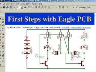
First Steps with Eagle PCB
Learn to create a basic circuit schematic diagram using Eagle software. Follow step-by-step instructions to design a circuit layout, add components, wire connections, and save your project. Prepare for the next tutorial on creating and editing a PCB board. Access the full tutorial at pakuranga.school.nz.

First Steps with Eagle PCB
E N D
Presentation Transcript
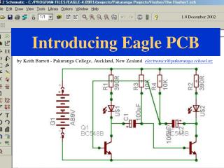
v 1.0 December 2002 First Steps with Eagle PCB by Keith Barrett - Pakuranga College, Auckland, New Zealand electronics@pakuranga.school.nz
First Steps with Eagle PCB? This is the second presentation and will show you how to produce a simple circuit schematic diagram using this software. If you first need an overview of the package click here to view presentation 1
How to use this presentation? It would be useful to have access to two adjacent computers. Install and run Eagle on one and this presentation on the other. . Alternatively, print the pages of this presentation and work through them with Eagle running on your PC. .
Creating a Project Run the Eagle program, when the control panel window appears click on File > New > Project
Creating a Project 2 Clicking new project opens a new folder in the projects section. You may want to rename the project at this point. The green button shows that this is the currently selected project
Creating a Project 3 Next click on File > New > Schematic
On this screen you create the circuit schematic diagram. . . . . Creating a Project 4 The file and viewing tools are along the top The selection and editing tools are here The drawing tools are here. Roll the cursor over the icons to see the function labels. A brief desciption of each function will appear here.
Next click on “add” to open the library window. Then click on “rcl” to open this component library. Creating a Project 6
Double Click to select this component (1/2 watt resistor 9mm long 10mm spacing) Click to open this component library (resistors- european) This symbol will appear on the schematic screen. Place it by clicking the mouse. Creating a Project 7
Creating a Project 8 This is what the screen should look like (you may have to zoom in to get it this size!) Having placed the first component you need to get a few more. Click on the add icon each time to open the library and choose a few more. . .try finding a 9V battery and an led. The delete icon is here if you need to remove objects.
Creating a Project 9 Move the components around the screen using this (move) key. You can edit the labels here
Creating a Project 10 “Wire” the components together using this key. click the mouse to start, change direction and double click (or esc) to finish a connection.
Creating a Project 11 Place “junctions” where wires meet the components. When you have a complete circuit SAVE it!
End of presentation 2 The next presentation shows you how to create and edit a pcb board from the circuit shown in this presentation. The circuit schematic can be downloaded as “easy example 1.sch” from: http://www.pakuranga.school.nz/depart/electronics/eaglepcb